


This post is also available in:
 German
A few weeks ago, I described in the blog https://vrealize.it/2025/06/02/vcf-nsx-edge-setup-aus-netzwerksicht/ how the NSX Edges in VCF5.x are deployed via the SDDC Manager.
In my opinion, the interaction between the individual components has been improved in VCF9, making it more user-friendly. Some changes can also be seen in the interaction with NSX.
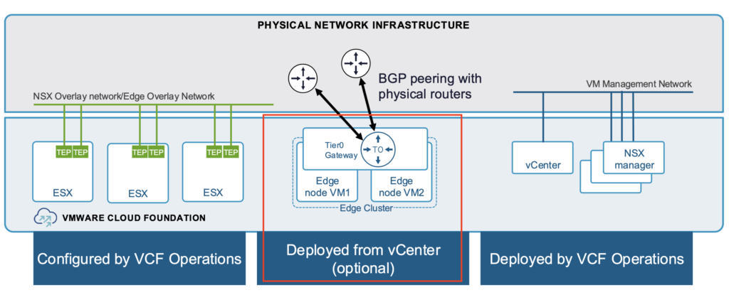
The installation of the NSX Manager and configuration of the TEP network on the ESX hosts is performed in VCF9 via VCF Operations (for VI WorkloadDomain) or VCF Installer for the Management Domain. Edges can be installed and configured directly from vCenter. However, installation and configuration via the NSX Manager is still possible.
The next Picture is given for the Workload Domain.
In this blog, I will describe the installation of NSX Edges via vCenter. Since the features of the NSX Edge and the way routing/switching works have not changed, I refer you to my previous blog post https://vrealize.it/2025/06/02/vcf-nsx-edge-setup-aus-netzwerksicht/ for details if you have any questions.
Target design
The target design of the NSX Edges and the T0 Gateway is identical to the design I described in the previous blog.
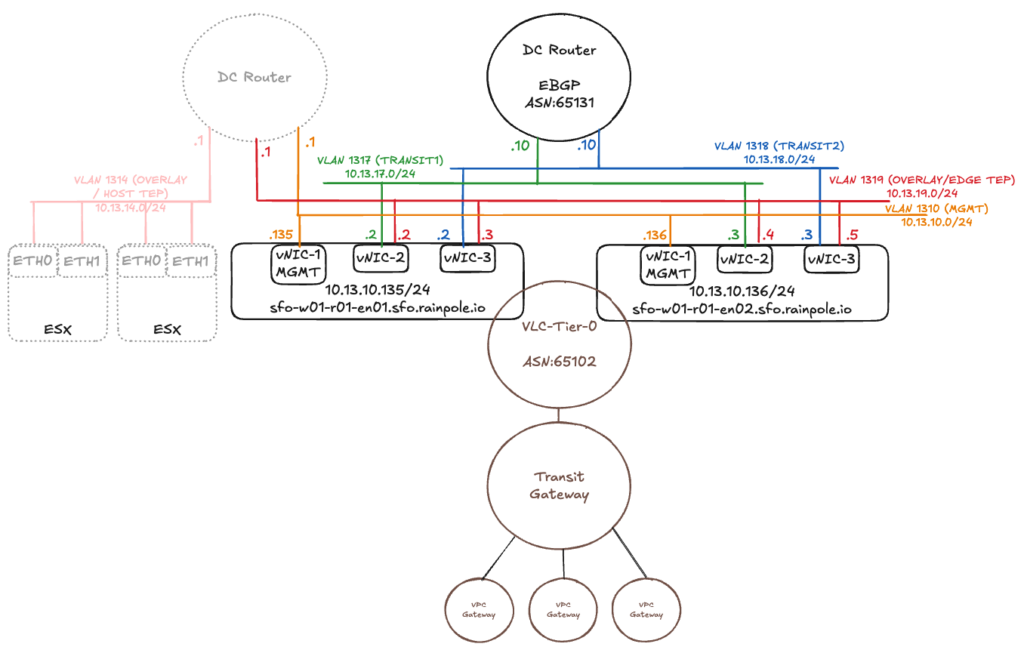
However, there is one change. There is a new Element named “Transit Gateway”. The Transit Gateway is similar to the well known T0 just without external Interfaces. And the T0 Gateway with external interfaces is reduced to an SR Component only (without DR). Transit gateways were introduced with VCF9 and are used to connect multiple VPCs in a project. A Tier1 Gateway is the counterpart of the VPC Gateway in the VPC Networking Model.
More Details can be found here: https://community.broadcom.com/applications-networking-security/blogs/luca-camarda/2025/06/23/vcf-virtual-networking-technical-reference
In VCF9, VPCs (Virtual Private Clouds) can also be deployed directly from vCenter. I described the VPC and project setup in the following blog post -> https://vrealize.it/2025/02/10/vpc-networking-with-vcf-nsx/
For the native VPCs (created from the vCenter), the Transit Gateway is used instead of the T1 Gateway.
The NSX Edge VMs are installed on the hosts where the workload VMs are located. If the ESXi server only has two physical network cards, the Geneve Overlay tunnel can either terminate at the physical network cards or be passed through to the Edge component and terminated there. However, both of these options mean that the tunnel endpoint cannot be available to both workload VMs and the NSX Edge at the same time.
For the configuration to work, the TEPs of the Edge VMs could be located on a different IP network than the TEPs of the ESXi servers and connected to each other via an external router. In VCF9 you can also use the same IP Network for Host TEP and Edge TEP (in my example I am still using seperate Networks for HOST TEP and Edge TEP). In the example above, the ESXi servers are in the overlay network 10.13.14.0/24 (VLAN 1314) and the Edge VMs are in the overlay network 10.13.19.0/24 (VLAN 1319). There are also configuration options for running the TEPs of the ESXi servers and the Edges on the same IP network. However, I will not discuss these options in this blog, as VCF requires the configuration path with two different TEP networks.
The vNIC-2 and vNIC-3 interfaces handle the workload traffic. Both interfaces are connected to the overlay network and establish a tunnel to the ESXi servers. On the two vNICs, the interfaces are configured for routing via different VLANs.
Requirements
The following requirements must be met for the setup:
- The workload domain was created via the SDDC Manager.
- External routers were configured and transit IP addresses were specified.
- The routing protocol (Static/BGP) was selected and configured on the data center routers.
- VLANs for the NSX Edge Overlay were configured and have an MTU size of at least 1,700.
- Routing between the host and Edge Overlay network is possible.
- DNS entries are in place.
Setup
The configuration is not done via the SDDC Manager or in VCF Operations, but directly via the vCenter of the respective workload domain.
(If the workload domain has just been created, you may need to create the port group for the Edge management interface and the associated VLAN. In my case, it is the port group “sfo-w01-cl01-vds01-pg-vm-mgmt” with VLAN 1310.)
After successfully logging in to the vCenter, the configuration task is located under Networks -> Network Connectivity.
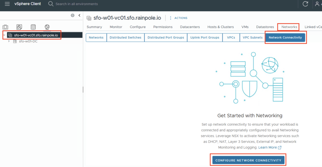
The configuration process is then started via “CONFIGURE NETWORK CONNECTIVITY”.
A new input screen will open, and the first step is to specify the gateway type. For most applications, the “Centralized Connectivity” type should be selected, as this provides services via the NSX Edges (DHCP, NAT, Layer 3 services, and network monitoring and logging).
There are use cases where distributed connectivity is required. In this case, communication to the data center occurs directly from the host into a VLAN network, thus bypassing the NSX Edge component. This increases performance, but only the DHCP and External IP services are available.
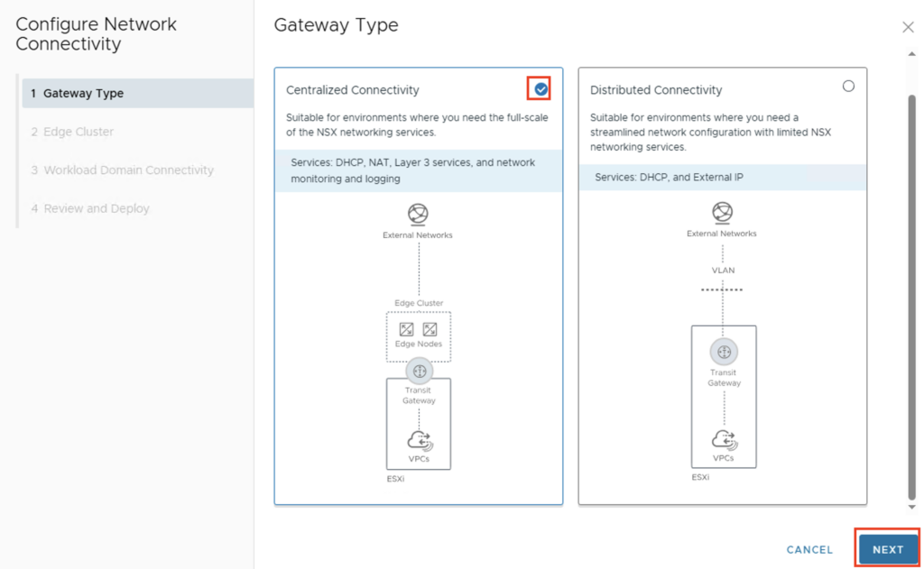
Since I want to use all functions in my use case, we select “Centralized Connectivity” and go to the next configuration step via “NEXT”.
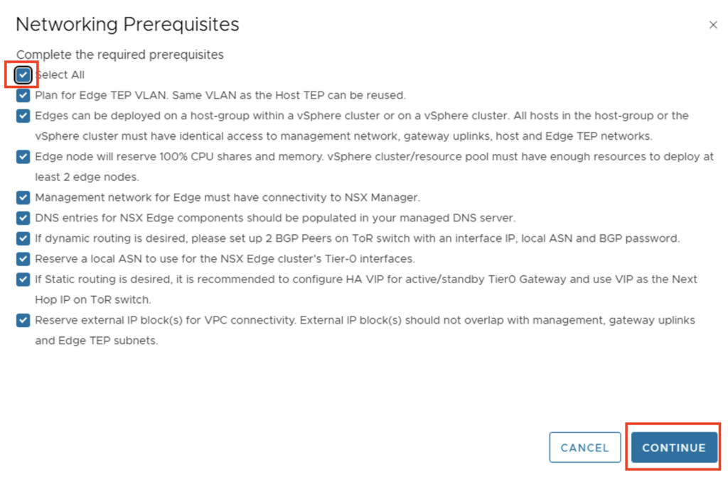
At this point you should check again whether all requirements are met and confirm this.
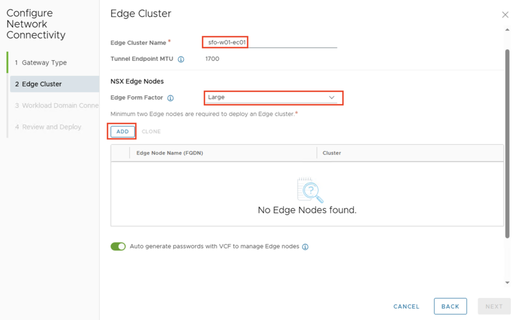
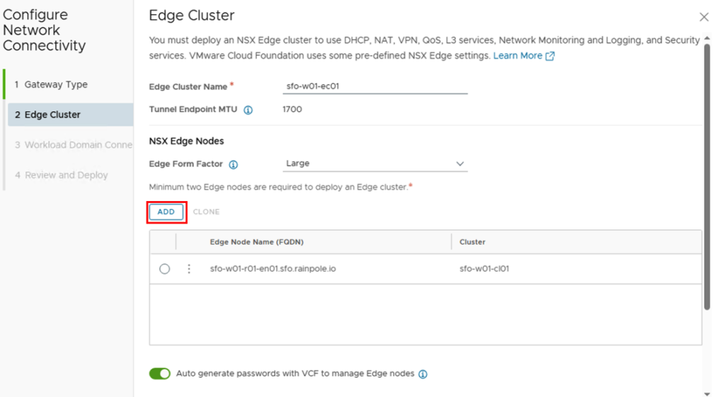
We’ll now be prompted to configure the Edges. We’ll start by giving the Edge Cluster a name and selecting the Edge form factor. We’ll then add the first Edge using “ADD.”
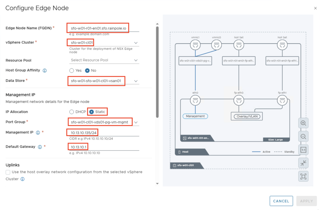
Ideally, the edge nodes should already be registered on a DNS server. The following values must, of course, be adjusted individually for each environment:
- Edge Node Name: sfo-w01-r01-en01.sfo.rainpole.io
- vSphere Cluster: sfo-w01-cl01
- Data Store: sfo-w01-sfo-w01-cl01-vsan-01
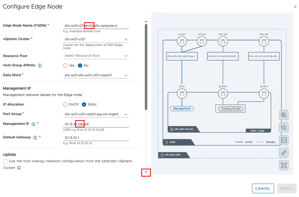
- Management IP
- IP Allocation: Static (kann natürlich auch über DHCP erfolgen)
- Port Group: sfo-w01-cl01-vds01-pg-vm-mgmt (mgmt VLAN)
- Management IP: 10.13.10.135/24
- Default Gateway: 10.13.10.1
INFORMATION: In Case you want to use the same Network for Host and Edge TEP you need to enable NSX on DVPG on Cluster Level in NSX.

… and activate the checkbox Uplinks – “Use the host overlay network configuration..”
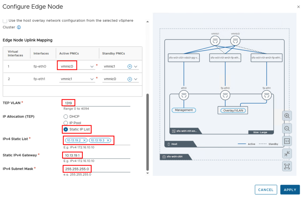
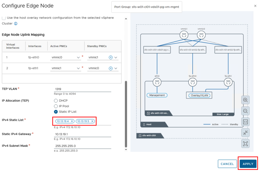
Next, the uplinks are mapped, and both the VLAN of the overlay network and the IP addresses are defined. I’m working with static IP addresses, so I selected “Static IP List” for IP Allocation and manually entered the two IP addresses for the tunnel endpoints.
The “APPLY” button saves the configuration of the first Edge and we can enter the parameters for the second Edge using the “ADD” button.
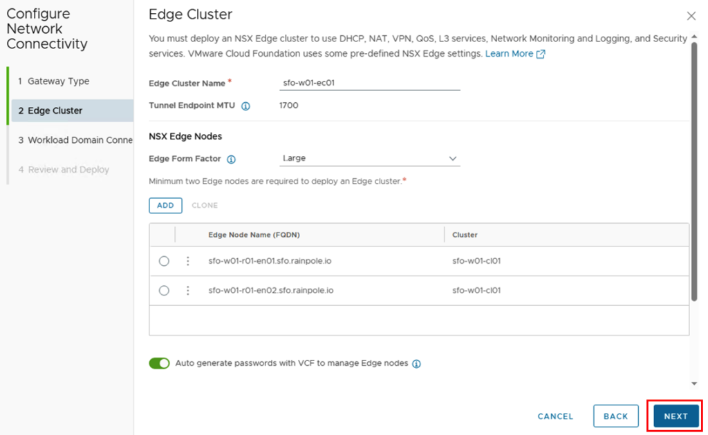
For the second edge node, the FQDN and IP addresses for the management and tunnel endpoints will change. The other parameters should remain identical.
We can now move on to the next step by clicking on “NEXT”.
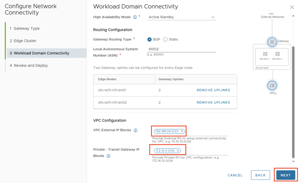
For Workload Domain Connectivity, the parameters for the T0 gateway are entered.
!!! If the deployment is used for VKS (vSphere Kubernetes Services), the “High Availability Mode” must be set to Active/Standby !!!
The parameters for my deployment are as follows:
- Gateway Name: VLC-Tier-0
- HA Mode: Active/Standby (ich möchte später VKS ausrollen)
- Gateway Routing Type: BGP
- Local ASN: 65102
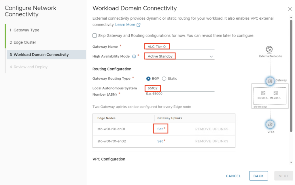
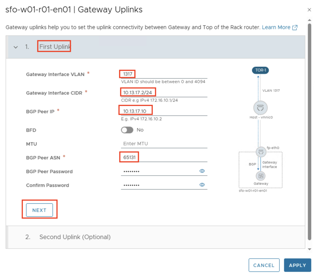
The uplink interfaces between the T0 gateway and the external data center router are then configured via Gateway Uplinks -> Set. The following parameters apply in my environment:
First Uplink
- GW Interface VLAN: 1317
- GW Interface CIDR: 10.13.17.2/24
- BGP Peer IP: 10.13.17.10
- BPG Peer ASN: 65131
- BGP Peer Password: Identisch mit dem externen BGP Router
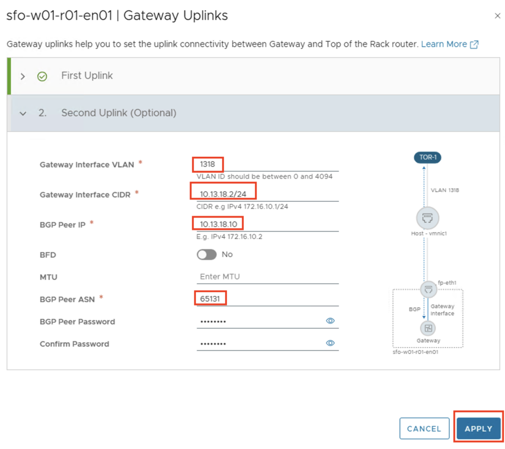
Second Uplink
- GW Interface VLAN: 1318
- GW Interface CIDR: 10.13.18.2/24
- BGP Peer IP: 10.13.18.10
- BPG Peer ASN: 65131
- BGP Peer Password: Identisch mit dem externen BGP Router
The second edge node is then also configured.
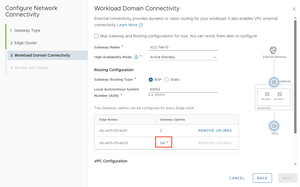
The IP addresses of the second Edge must of course be adjusted.
First Uplink
- GW Interface VLAN: 1317
- GW Interface CIDR: 10.13.17.3/24
- BGP Peer IP: 10.13.17.10
- BPG Peer ASN: 65131
- BGP Peer Password: Identisch mit dem externen BGP Router
Second Uplink
- GW Interface VLAN: 1318
- GW Interface CIDR: 10.13.18.3/24
- BGP Peer IP: 10.13.18.10
- BPG Peer ASN: 65131
- BGP Peer Password: Identisch mit dem externen BGP Router
After both edges have been configured with the uplink interfaces, IP pools can be created for the native VPC.
In my lab environment, I have access to the network 192.168.24.0/23. Address spaces from this network will later be used to make them available externally (i.e., outside the NSX environment). This includes the NAT address for VMs located in a “private” or “transit” subnet, and for networks that should be accessible as public (i.e., outside the NSX environment).
The Private Transit Gateway IP block is not propagated externally and can be used when VMs from different VPCs need to communicate with each other. Since the IP block is not propagated, I’ll choose a larger space with the network 172.16.0.0/16.
Once the data has been entered, the configuration can be completed via “NEXT”.
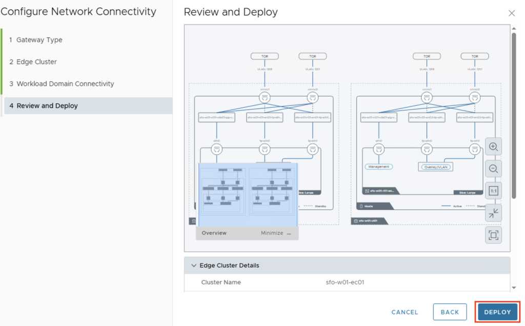
You will have another chance to view the configuration and click “DEPLOY” to start the installation and configuration.
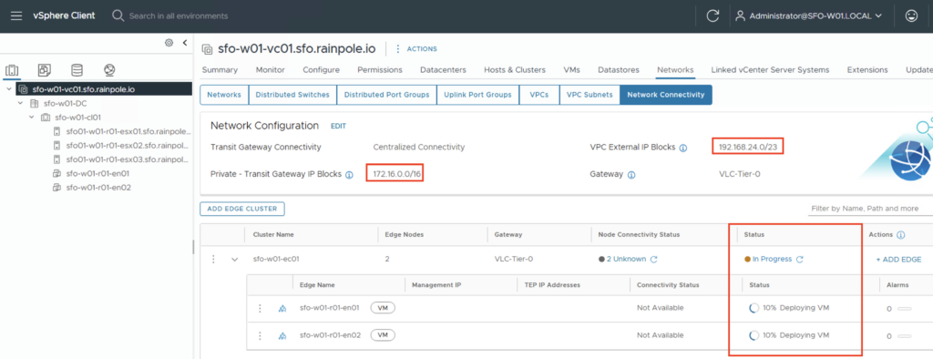
You’ll then return to the vCenter view and see how the Edge Cluster is being created. In the Network Configuration, you’ll also see the information about the IP blocks we created in the last step. Depending on your environment, the installation may take a moment.
Check configuration
Once the deployment has been successfully completed, we can connect to the NSX Manager and check whether the connections between the T0 gateway and the external router have been established properly. After successfully logging into the NSX Manager, we should check the BGP neighbor status. This can be found under Networking -> Tier-0 Gateways -> ROUTER-NAME -> BGP -> BGP Neighbors.
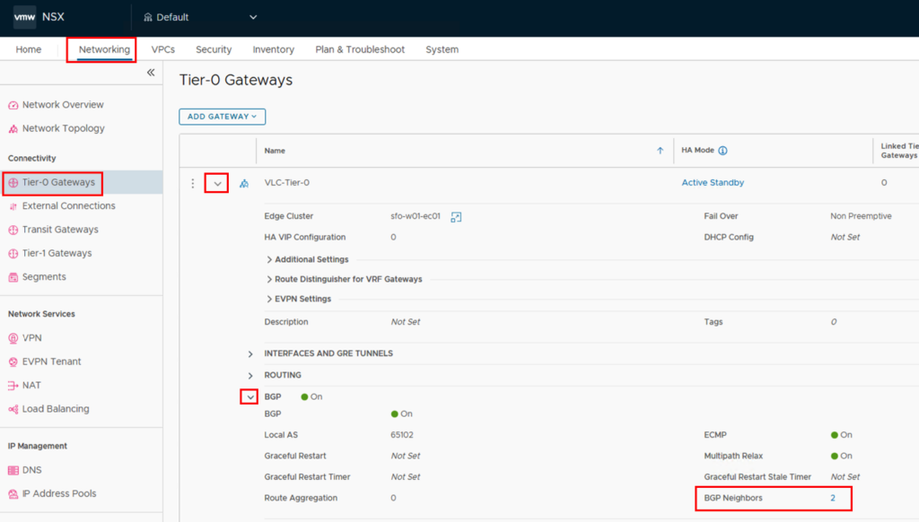
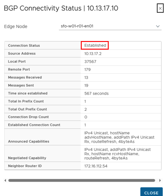
In the new window you can expand the BGP Neighbors and find the “BGP CONNECTIVITY STATUS” on the right side.
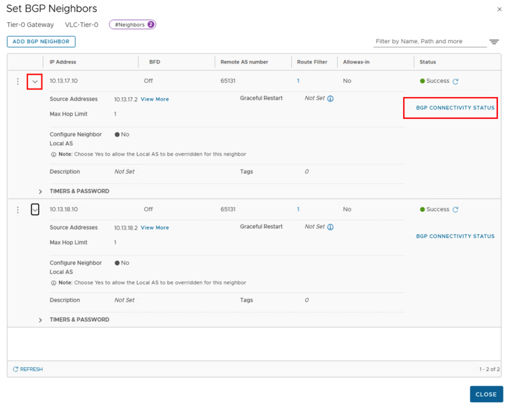
The status of all connections should be “Established”.
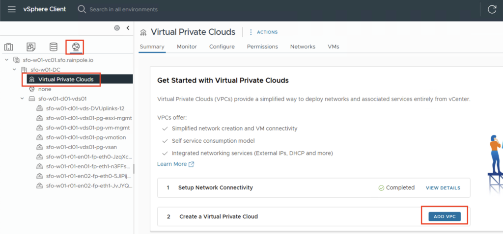
Create VPC
Now it’s time to create our first VPC. To do this, go back to vCenter and click on the Network tab -> Virtual Private Clouds -> “ADD VPC”
You need to specify a name for the VPC and an IP address range that only exists within the VPC. If you create multiple VPCs, this network can be identical in all VPCs (overlapping). Here, too, I’m choosing a large IP address range of 172.31.0.0/16.
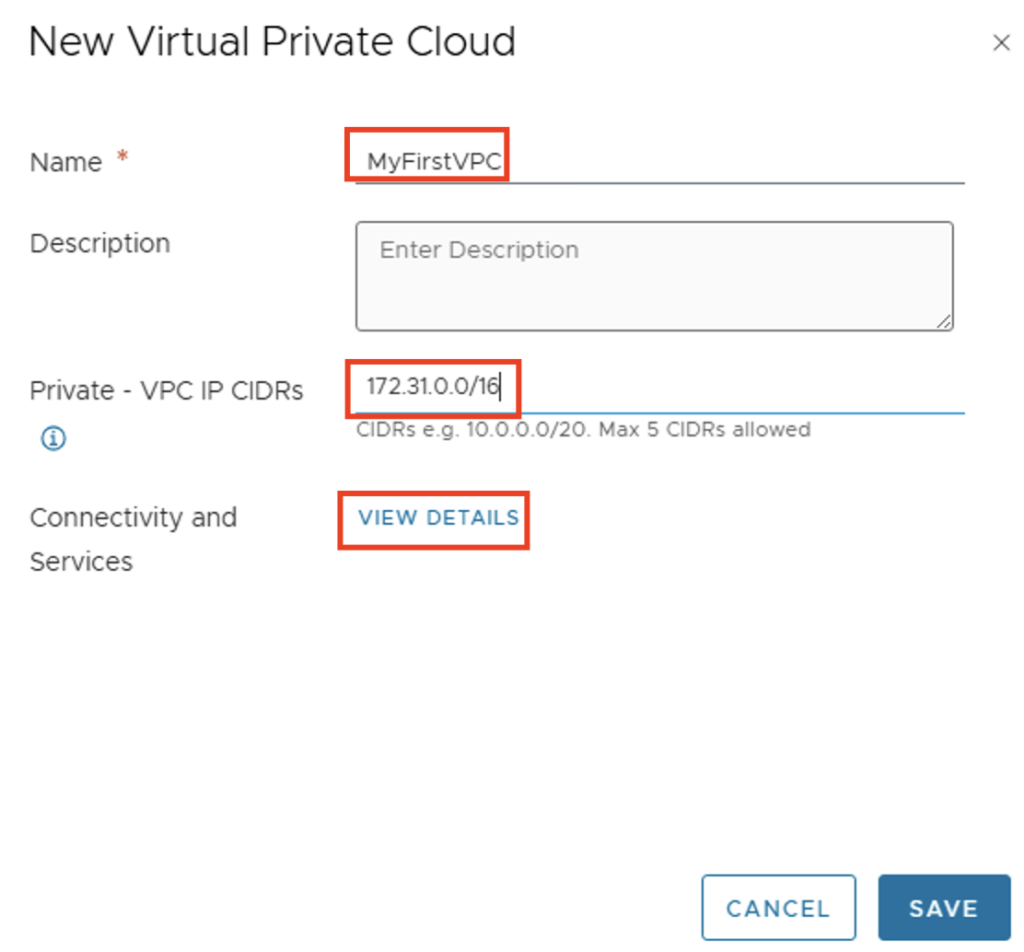
You can check the VPC preferences via “VIEW DETAILS” under Connectivity and Services.
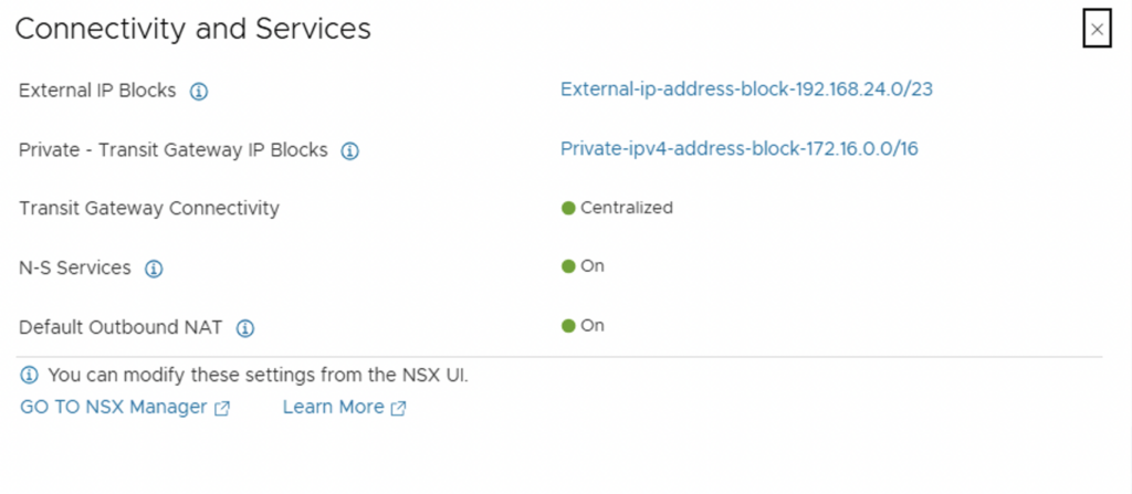
The IP blocks we created during the initial configuration will be used. NAT will also be automatically enabled. This is necessary so that VMs located in a “private network” or “private transit network” cannot be directly reached from the outside, but can still communicate from the inside (e.g., to DNS, NTP, AD). After reviewing the information, we can close the window and create the VPC using the “SAVE” button.
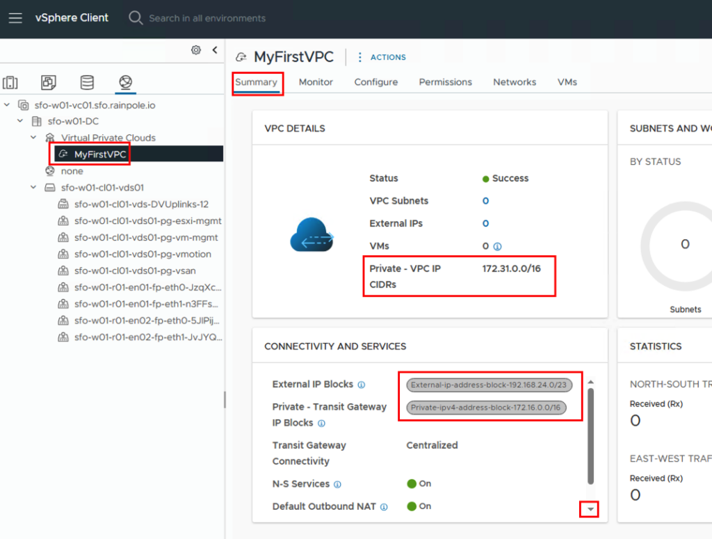
In the summary, we see information about the IP blocks and the number of configured networks, which is currently set to 0. If you scroll down in the “CONNECTIVITY AND SERVICES” field, you’ll also see the default outbound NAT address.
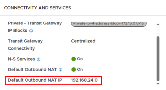
The NAT IP is provided from the external IP pool (192.168.24.0/23). Since this is a /32 address, it can also end with a 0 and will still be propagated by all routers.
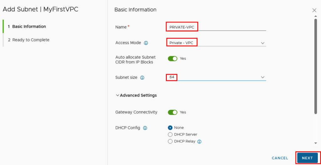
Next, we can create networks in the VPC. This is done via ACTIONS -> New Subnet…
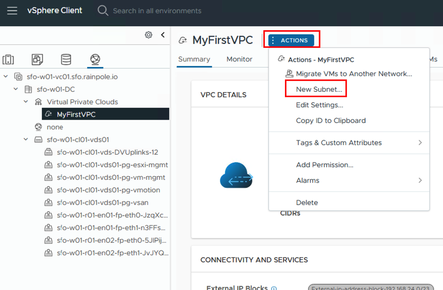
The subnet needs a unique name within the VPC. Next, select the access mode. This can be “Private – VPC,” “Private – Transit Gateway,” or “Public,” depending on whether the network should be accessible from outside, only within a VPC, or between VPCs.
To make things easier for the user, there is no need to enter a network with a subnet mask; instead, the user simply determines the number of available addresses that should be available in the network via the subnet size.
If you want to use DHCP, you can either store a DHCP profile in NSX (DHCP server) or forward to a DHCP server via DHCP relay.
In my environment I have created a subnet in private, private transit and public.
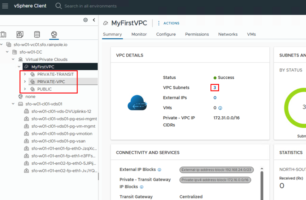
In the Networks tab, you can see the details of the individual networks I’ve created. The respective IP CIDR shows that a network was created from the predefined IP pools, depending on the network type.

Another view option can be found under -> Configure -> Settings -> Topology
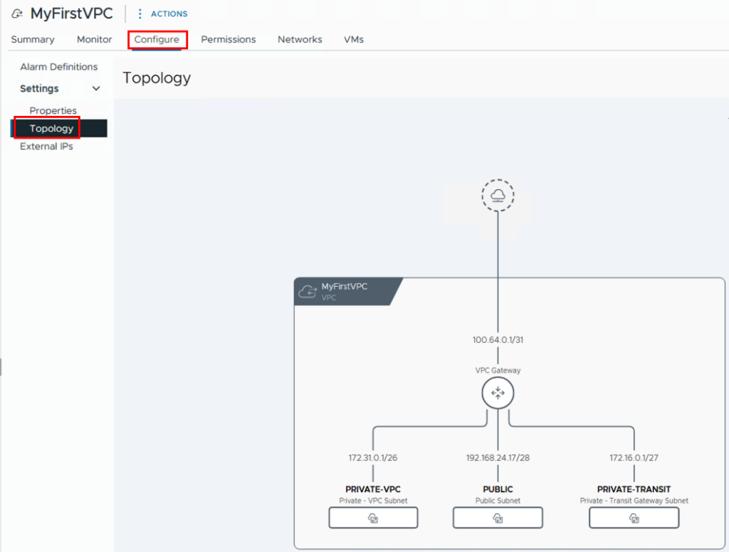
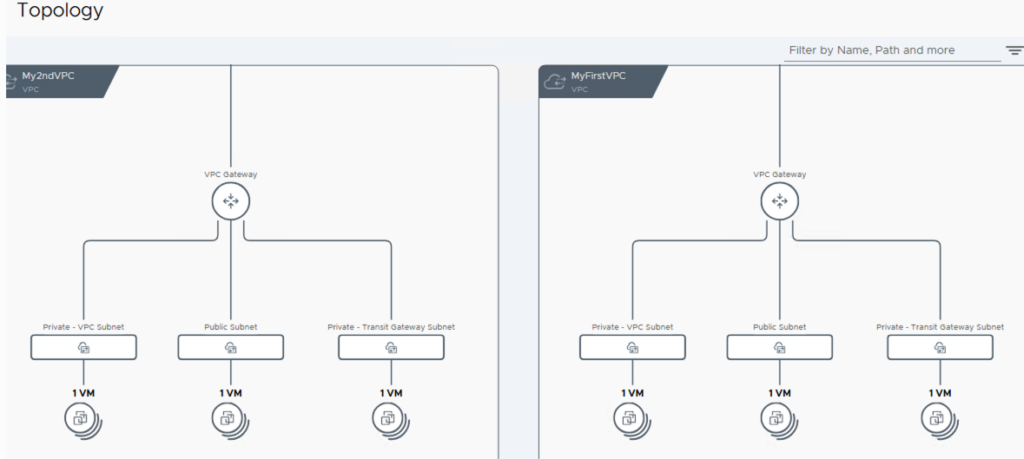
Once the networks have been created, we can assign networks to the VMs and test them. If we also want to test inter-VPC communication, we need a second VPC. I created this one with the name My2ndVPC and also configured the three networks. As you can see in the topology, I also selected 172.31.0.0/16 for the IP range of the private networks, thus creating overlapping IPs. This isn’t a problem, however, since the IPs from the private network are only relevant within the respective VPC.
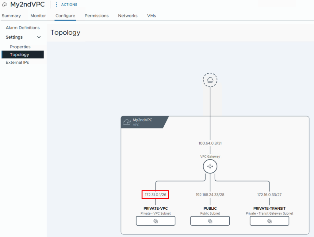
You can view a complete view of all VPCs via Virtual Private Clouds -> Configure -> Topology. Here you can also see that both VPCs are connected via the Transit Gateway.

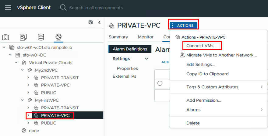
Now it’s time to connect VMs to the created networks. Once you’ve selected a subnet, you can add the VMs directly via ACTIONS -> Connect VMs. Of course, you can also do this via the configuration settings on the VM.
First, the VMs are selected and then the network adapters (if the VM has several configured)
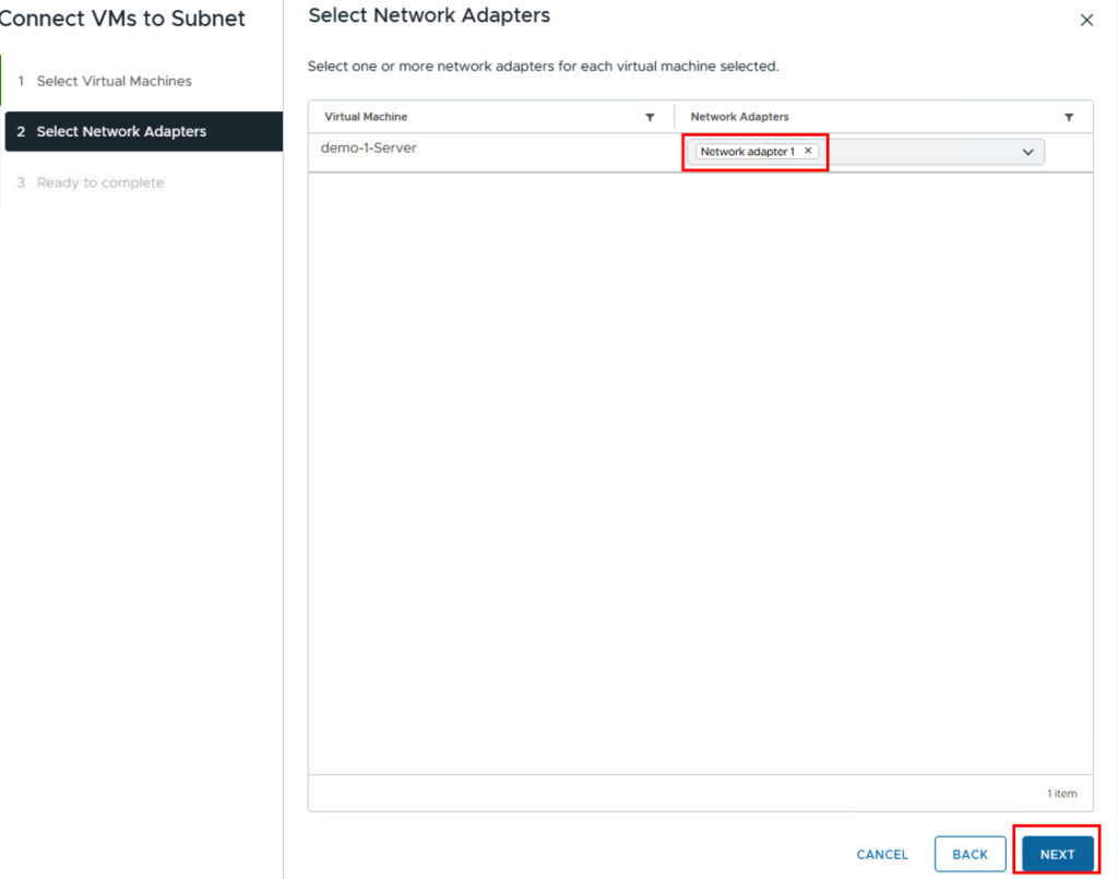
We then repeat this process for the other networks. Eventually, there should be a VM in each network.
Here is an overview of my VMs
| VM Name | VPC / VPC SUBNET | IP Adresse |
| demo-1-server | MyFirstVPC/PRIVATE-VPC | 172.31.0.3/26 |
| demo-2-server | MyFirstVPC/PRIVATE-TRANSIT | 172.16.0.3/27 |
| demo-3-server | MyFirstVPC/PUBLIC | 192.168.24.19/28 |
| demo-4-server | My2ndVPC/PRIVATE-VPC | 172.31.0.3/26 |
| demo-5-server | My2ndVPC/PRIVATE-TRANSIT | 172.16.0.35/27 |
| demo-6-server | My2ndVPC/PUBLIC | 192.168.24.35/28 |
Test 1: SSH from my PC (external) to demo-3-server (192.168.24.19) in the public network.
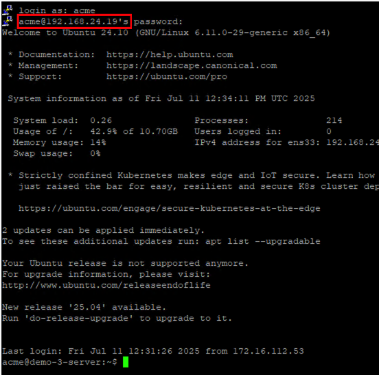
As expected, I can access the server via the public IP address.
Test 2: Ping from demo-3 server to servers demo-1 and demo-2 as well as demo-5 and demo-6

The server demo-3-server can reach all other servers. The reason demo-4-server cannot be reached is because this server has the same IP address as demo-1-server in the local VPC.
Test 3: Ping from demo-1-server and from demo-2-server to an external address (8.8.8.8)
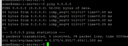
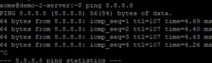
The servers can successfully reach external IP addresses.
Test 4: Ping from my PC (external) to demo-1-server and demo-2-server.
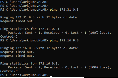
Both private and private-transit networks are not accessible from an external address.
Summary
VCF9 enables easy deployment of the NSX infrastructure. Furthermore, native VPCs allow users to consume networks from vCenter and choose between different network types as needed. This allows users to access resources faster (agility), while the network administrator still retains control over the IP address ranges that can be used (robustness).

- VCF9 NSX-Edge Setup – What has changed - 11. July 2025
- VCF NSX-Edge setup from a network perspective - 2. June 2025
- VCF Workload Domain Setup from a network perspective - 2. June 2025
Hi Daniel
please get in contact with me, we should make a few correction on this page
thanks
Oliver