


This post is also available in:
 German
In my previous post (https://vrealize.it/2025/06/02/vcf-workload-domain-setup-aus-netzwerksicht/), I described how to create a workload domain using the SDDC Manager and what is required from a network perspective. In this post, I will discuss the steps required to install the NSX Edges (including routing). The NSX Edges, in conjunction with the Tier-0 logical gateway, form the bridge between the overlay networks (within the SDDC) and the underlay networks (outside the SDDC).
Before we look at the target design and configuration, I would like to briefly explain how the Edge and the logical router work together.
NSX Edge Function
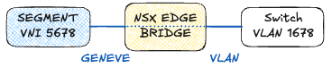
With NSX, virtual network infrastructures can be created on top of an existing network infrastructure. The GENEVE (Generic Network Virtualization Encapsulation) protocol is used for transport.
To enable communication between end devices in the overlay and end devices in the traditional VLAN-based network, a box is required that can translate between the two worlds. This task is performed by the NSX Edge, which is available both as a virtual device (OVA file) or for a bare-metal server (ISO file).
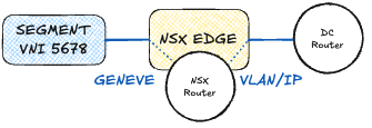
Edge Routing
The NSX Edge typically also handles routing and is connected to the external router in the data center. Routing can be static, via the OSPF routing protocol, or BGP. BGP is the recommended routing protocol because it offers the most options. For configuration, a logical router (Tier-0 gateway) is connected to the NSX Edge cluster and configured via the NSX Manager. This means that the NSX Edges are responsible for both converting the Geneve overlay into a traditional IP packet and for routing between the IP networks.
Routing and redundancy
To ensure smooth routing and prevent the failure of a single component from resulting in a total outage, the edges should be located on different ESXi servers and connected to two external routers via separate links. This ensures that the failure of a server, router, or individual links can be intercepted.
BFD (Bidirectional Forwarding Detection) should also be enabled to detect network errors between the data center router and the logical Tier-0 gateway as quickly as possible.
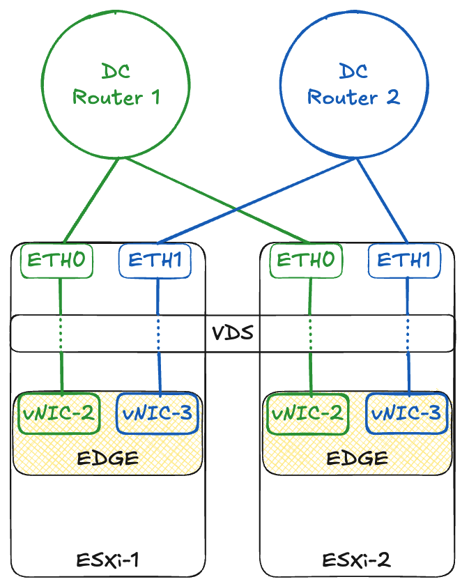
Port mapping to the physical interfaces is performed automatically during deployment.
Two transit IP networks in different VLANs are therefore required for the configuration.
vNIC-2 (green network) is located in the transit network 10.13.17.0/24 (VLAN 1317), and vNIC-3 (blue network) is located in the transit network 10.13.18.0/24 (VLAN 1318).
As already mentioned, a logical router (Tier-0 gateway) is also created, which can be used to configure routing. The two edges are grouped together in a cluster and connected to the logical router. In my example, eBGP is configured. For this, we need an AS number for the logical router and the AS number for the external data center router.
Additional routers (Tier-1 gateways) can be connected internally to the logical router. The transit networks between the Tier-0 gateway and the Tier-1 gateway are created automatically by NSX. Networks are carved out of the CIDR 100.64.0.0/16.
Target design
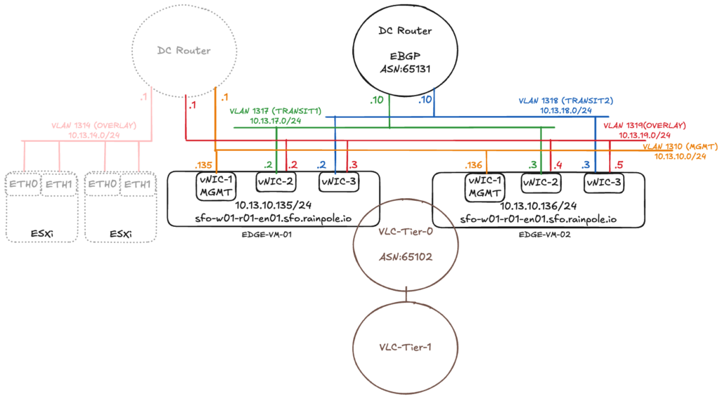
As mentioned at the beginning, in my previous post (https://vrealize.it/2025/06/02/vcf-workload-domain-setup-aus-netzwerksicht/) I showed how to create a workload domain using the SDDC Manager and configure the network overlay on the ESXi servers. The ESXi servers with the overlay network are slightly transparent on the left side of the diagram.
The NSX Edge VMs are installed on the hosts where the workload VMs are located. If the ESXi server only has two physical network cards, the Geneve Overlay tunnel can either terminate at the physical network cards or be passed through to the edge component and terminated there. However, both of these options mean that the tunnel endpoint cannot be available to workload VMs and the NSX Edge at the same time.
For the configuration to work, the TEPs of the Edge VMs must be located on a different IP network than the TEPs of the ESXi servers and connected to each other via an external router. In the example above, the ESXi servers are in the overlay network 10.13.14.0/24 (VLAN 1314) and the Edge VMs are in the overlay network 10.13.19.0/24 (VLAN 1319). There are also configuration options for running the TEPs of the ESXi servers and the Edges on the same IP network. However, I will not discuss these options in this blog, as VCF requires the configuration path with two different TEP networks.
The NSX Edges use a total of three virtual interfaces (vNICs). The vNIC-1 interface is the management interface with which the NSX Manager communicates, and SSH access can also be established.
The vNIC-2 and vNIC-3 interfaces process the workload traffic. Both interfaces are connected to the overlay network and establish a tunnel to the ESXi servers. On the two vNICs, the interfaces are configured for routing via different VLANs.
Requirements
The following prerequisites must be met for setup:
- The workload domain has been created using the SDDC Manager.
- External routers have been configured and transit IP addresses have been specified.
- The routing protocol (Static/OSPF/BGP) has been selected and configured on the data center routers.
- VLANs for the NSX Edge Overlay have been configured and have an MTU size of at least 1,700.
- Routing between the host and Edge Overlay network is possible.
- DNS entries are present.
Setup
Configuration is done via the SDDC Manager.
After logging in, go to the workload domain in which the edge cluster is to be created: Inventory -> Workload Domains -> “Name of the workload domain.”
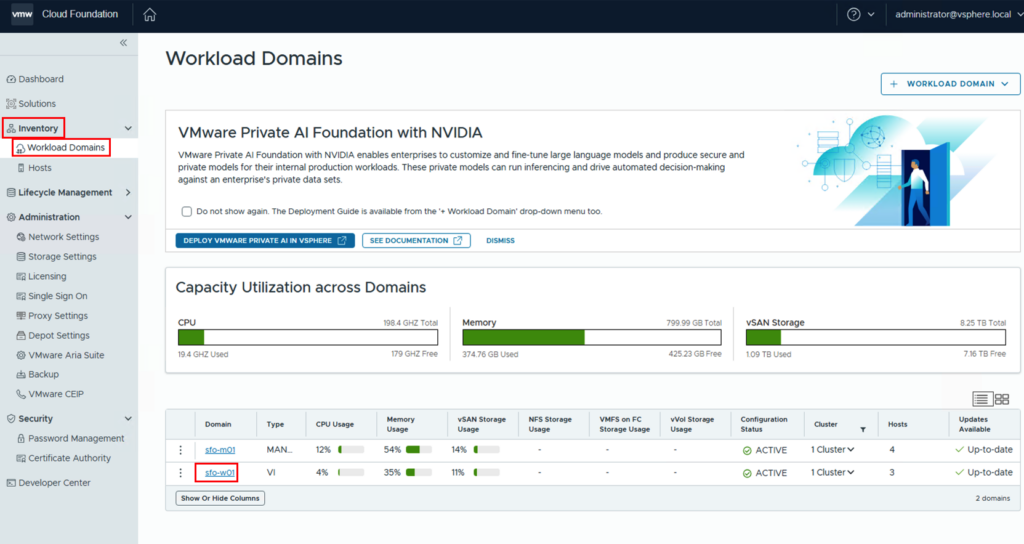
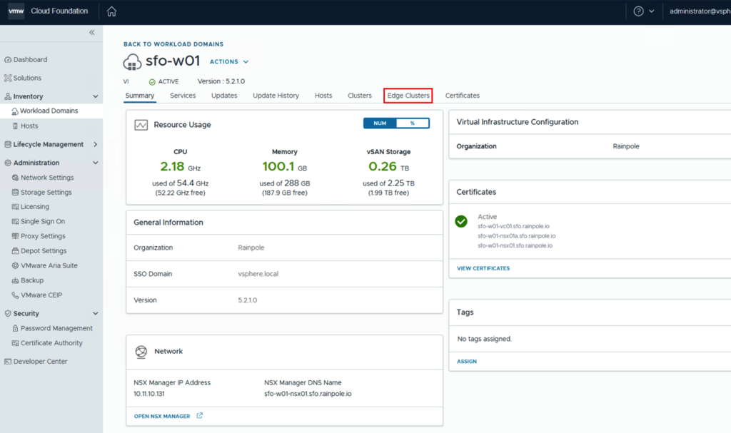
The settings are located under the “Edge Clusters” tab.
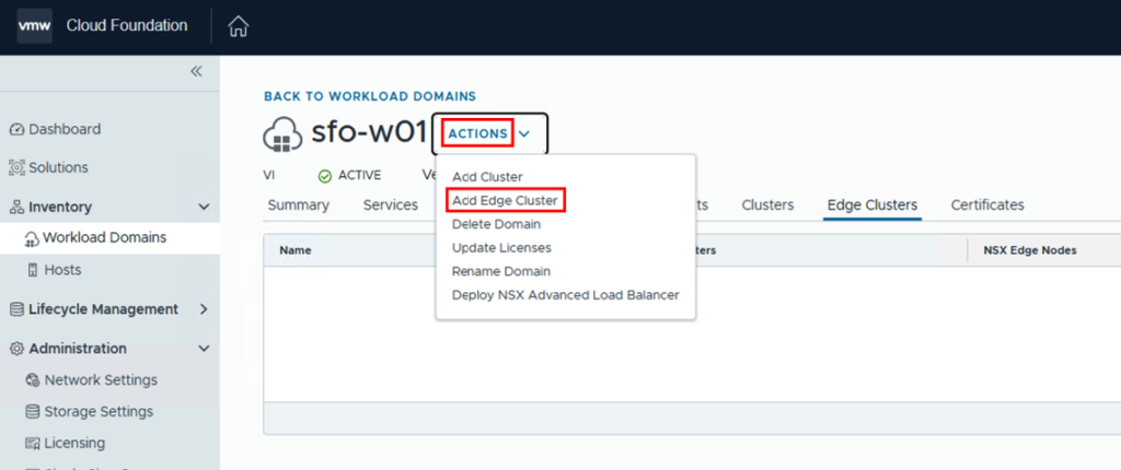
Via ACTIONS-> Add Edge Cluster, we can start the configuration.
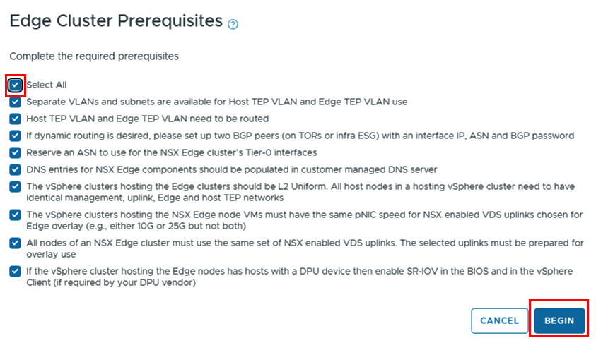
At this point, the requirements are displayed. If they are met, you can click the “Select All” button to check all the boxes and begin the configuration.
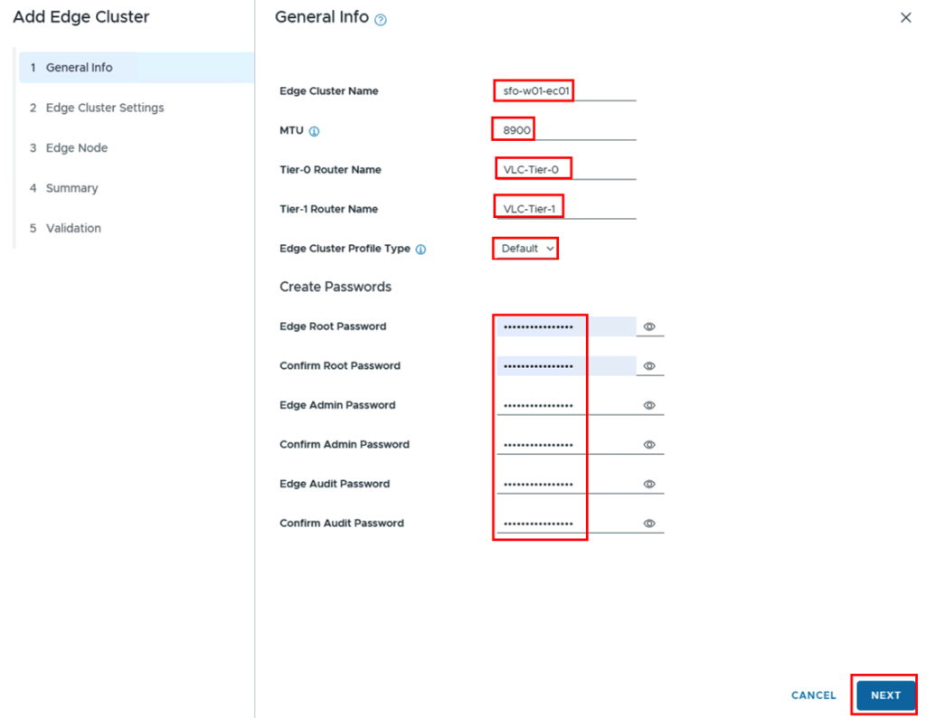
The general information is compiled and should be adapted to your own environment:
- Edge Cluster Name: sfo-w01-ec01
- MTU: 8900 (or minimum 1700)
- Tier-0 Router Name: VLC-Tier-0
- Tier-1 Router Name: VLC-Tier-1
- Edge Cluster Profile Type_ Default
- Passwords for the Edges.
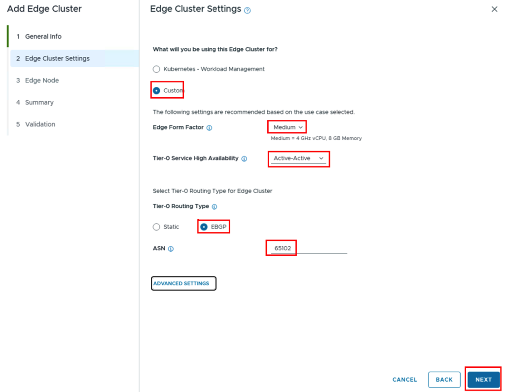
In the next tab, you can either select whether the edges will be used for Kubernetes, in which case the size would be determined automatically, or you can specify these parameters yourself using Custom. Under Tier-0 Service High Availability, you can specify whether the edges will operate in Active/Standby mode or Active/Active. Generally, all resources should be used (A/A).
Since we want to use EBGP, we select this and assign the ASN to be used on the logical Tier-0 gateway. The ASN of the counterpart (data center router) will be specified later.
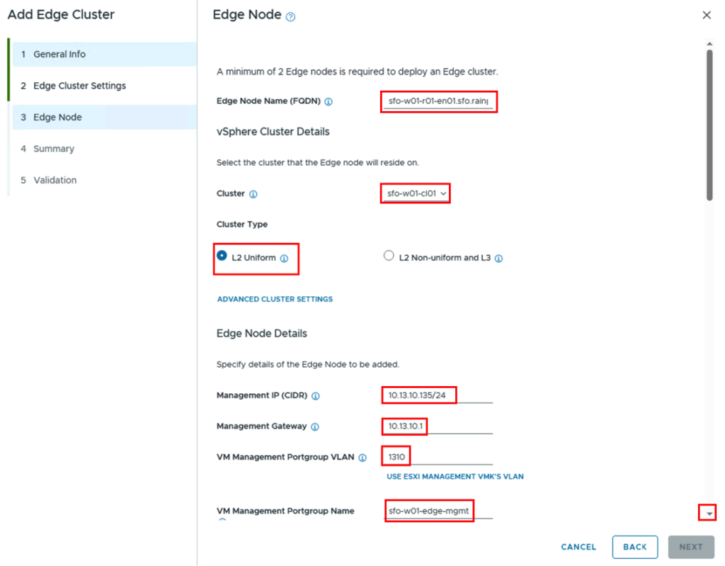
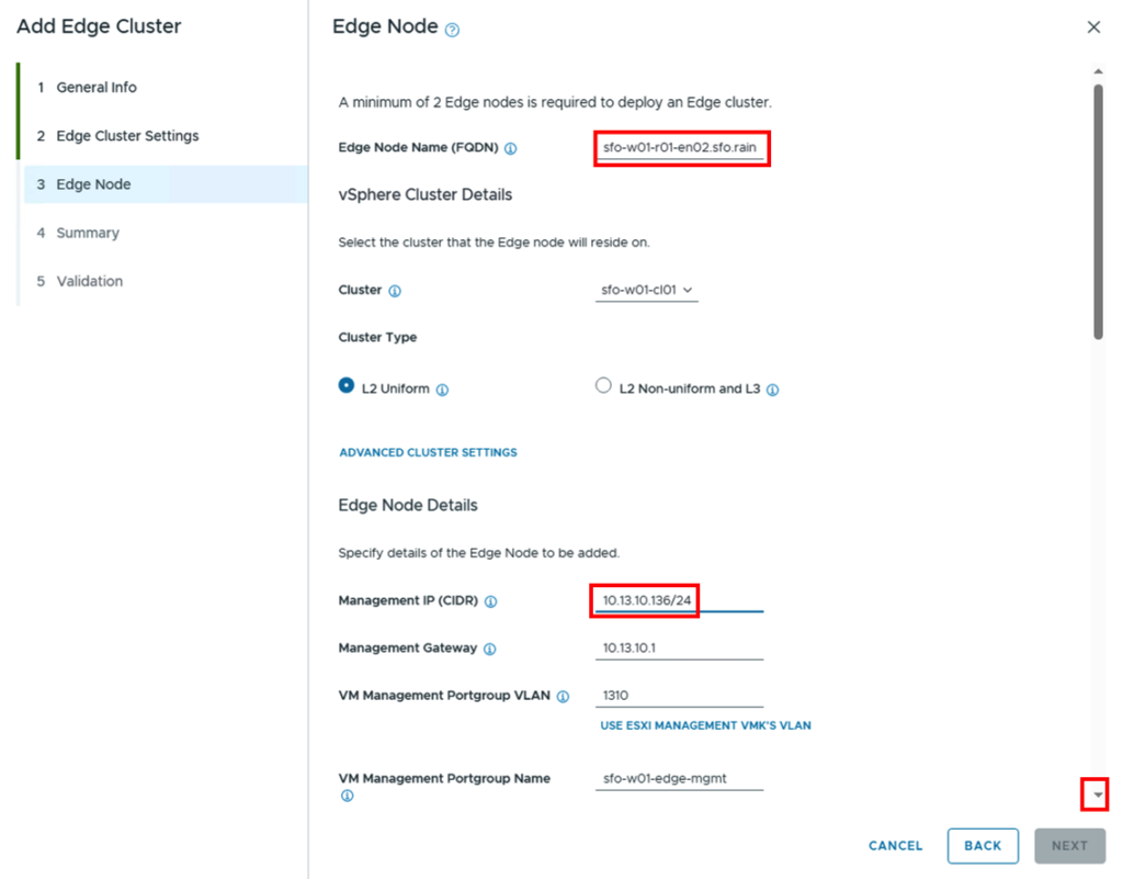
Next, the data for the two Edge Nodes is specified. In addition to the DNS name, you must select which cluster in the vCenter the Edge Nodes should be installed on.
The Edges are assigned a unique IP address, and since the VLAN and port group do not yet exist in the vCenter, you must also define the VLAN and a name for the port group.
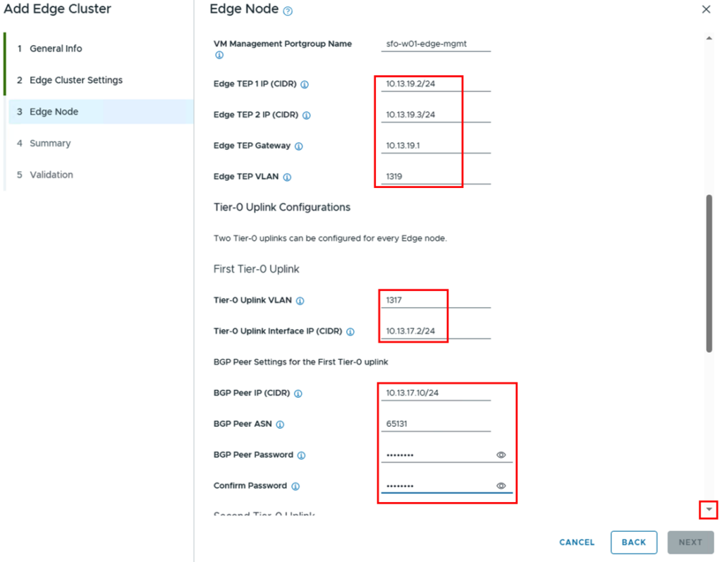
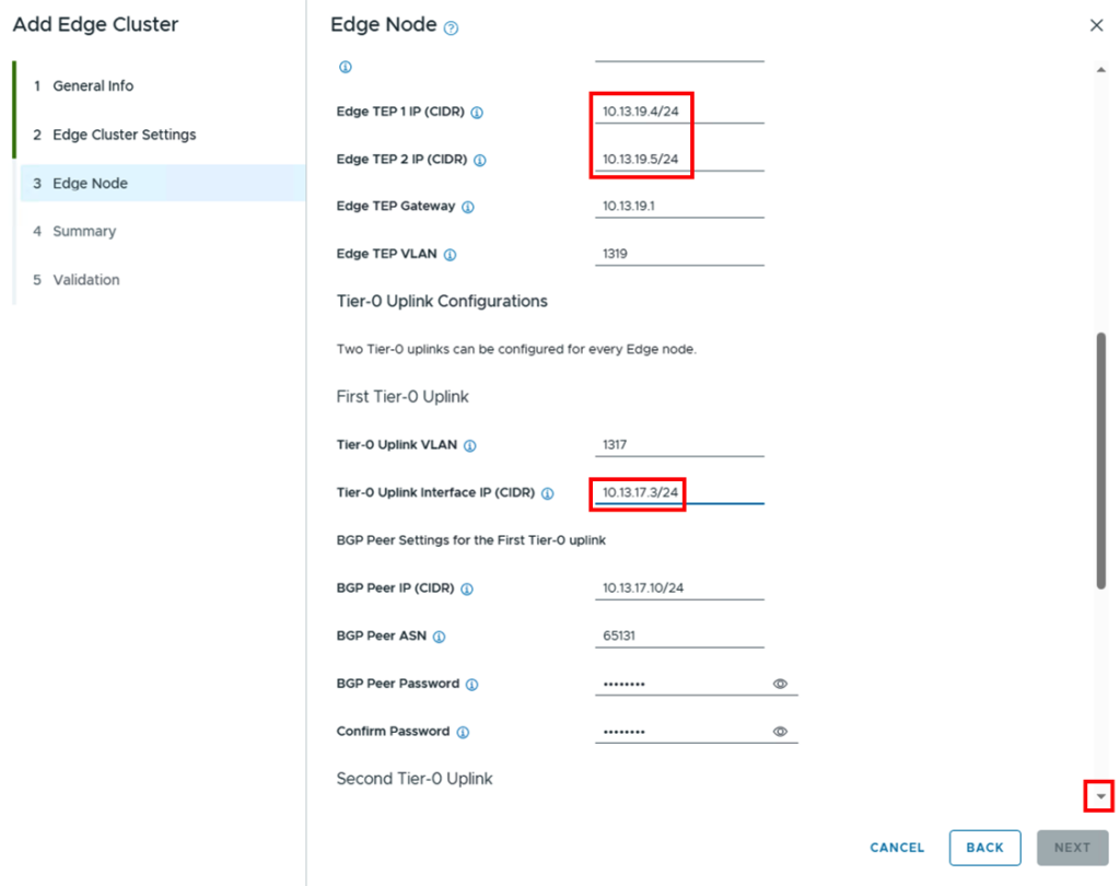
After scrolling down a bit, the fields for the overlay’s tunnel endpoint addresses and the VLAN to be used are entered next.
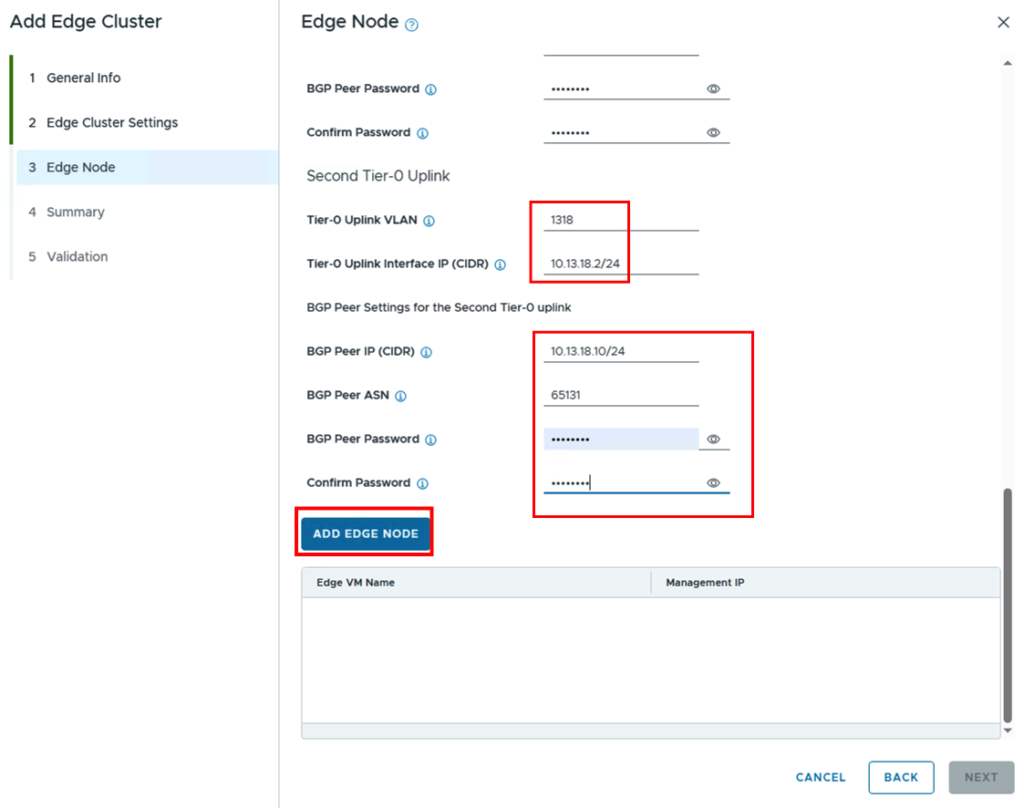
Then, the information for the transit networks (and VLANs) between the edge and the data center router is entered for the two uplinks.
For peering with the data center router, the peer IP address (i.e., the interface of the DC router) and the ASN are entered. If BGP is protected with a password, the password is also required, which must be identical in the BGP configuration on both the NSX edge and the DC router.
Once all data for the first edge has been entered, the edge is saved using the “ADD EDGE NODE” button.
The configuration of the second edge is then started via “ADD MORE EDGE NODES”.
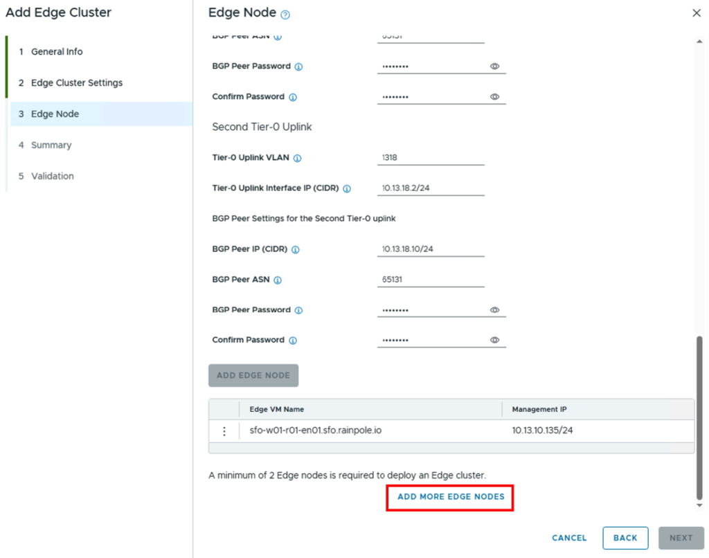
Thankfully, the data from the first edge node is transferred, and you only need to change the relevant fields.
This includes the DNS name and the IP address of the second edge node…
…the TEP IPs and the IP address of the uplink interface.
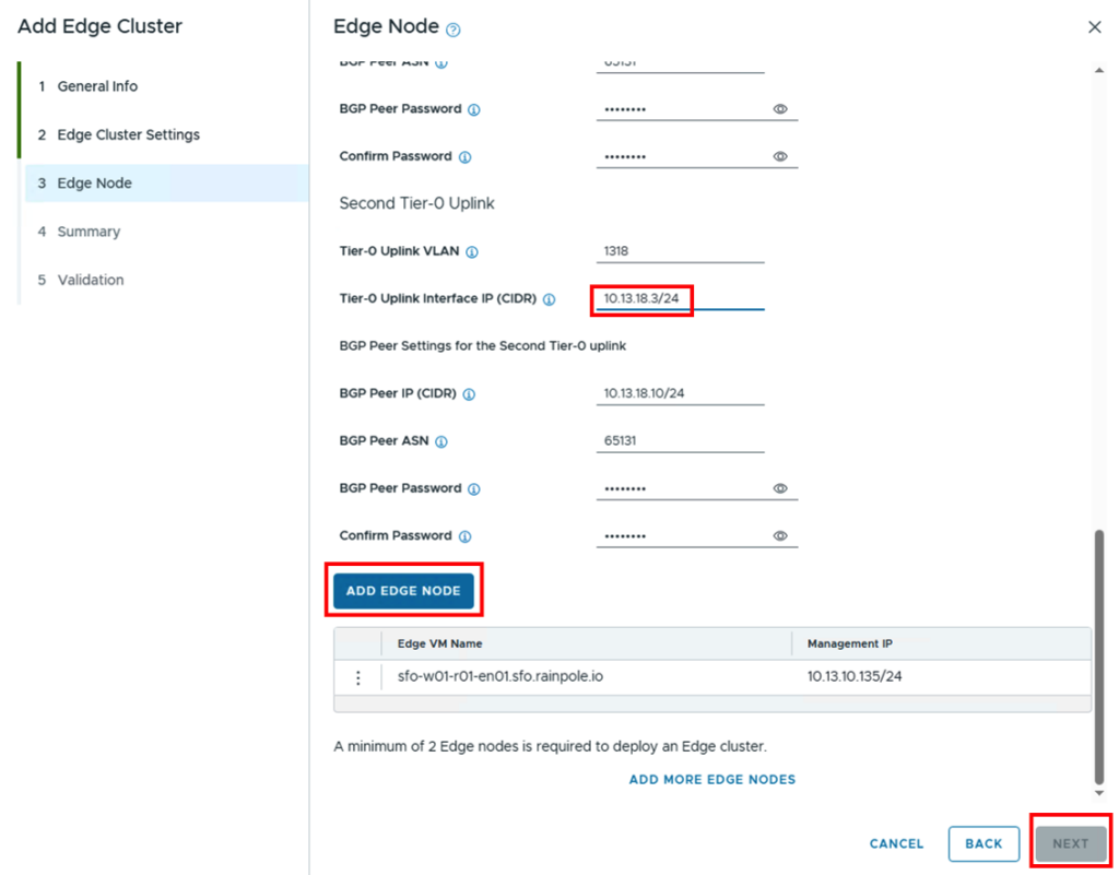
Afterwards, the second node can be added and via Next you can get to the overview where all the data is summarized again.
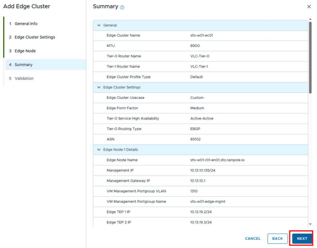
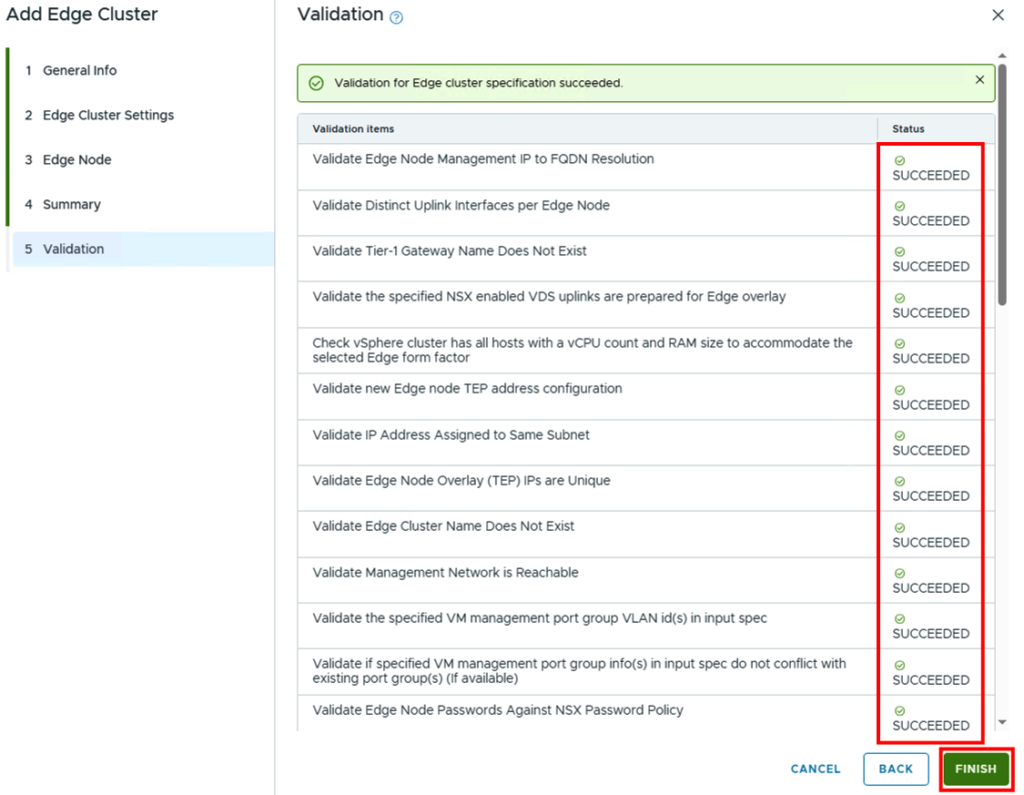
After all data has been checked again, validation can be started by clicking “NEXT.” If any discrepancies occur during validation, the SDDC Manager will display an error message and indicate where action is required. If all points are correct from the SDDC Manager’s perspective, deployment can be started by clicking “FINISH.”
Depending on the performance of the environment, installation takes between 15 and 45 minutes.
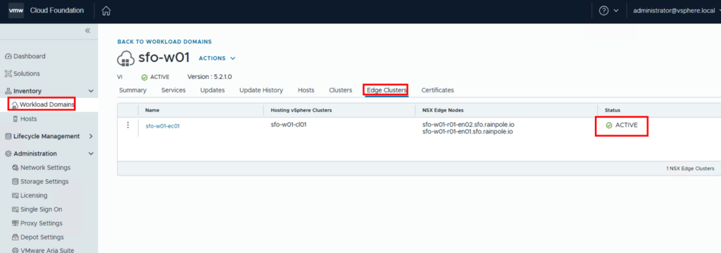
Verification
Once the configuration is successfully completed, the created NSX Edge cluster will appear as ACTIVE in the SDDC Manager.
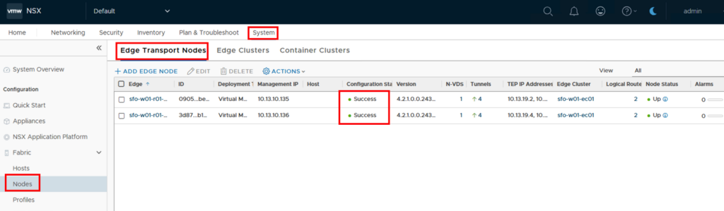
We can now go to the NSX Manager and check whether everything is working as intended. In the NSX Manager, we first look at the status of the Edge Nodes: System -> Nodes -> Edge Transport Nodes. The configuration status for both Edges should be set to Success.
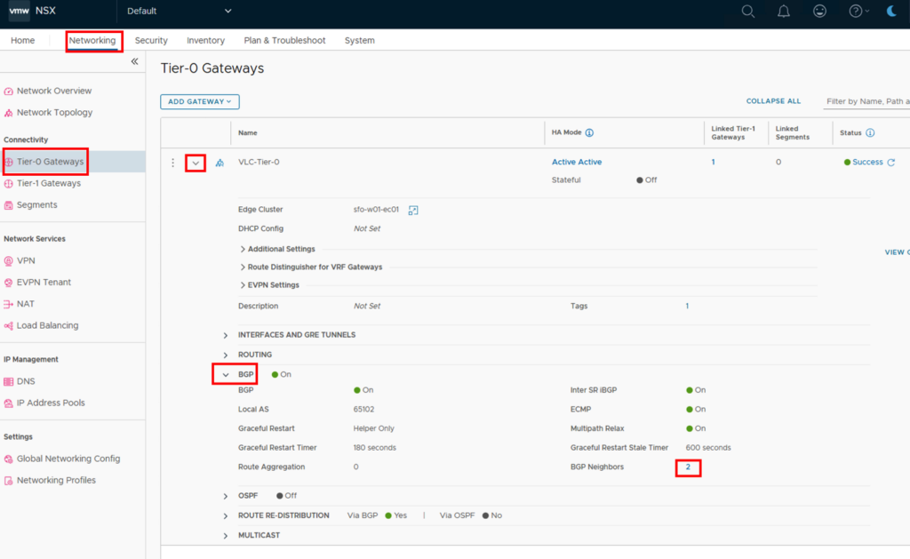
Additionally, the router should have been created in the NSX Manager under Networking -> Tier-0 Gateways. In the router, under BGP, you can see that two BGP neighbors are present. The blue 2 takes you to the BGP Neighbors configuration.
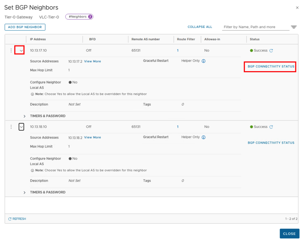
The status should be Success and you can access further details via “BGP CONNECTIVITY STATUS”.
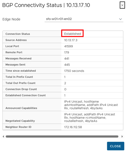
The connection status should show “Established”.
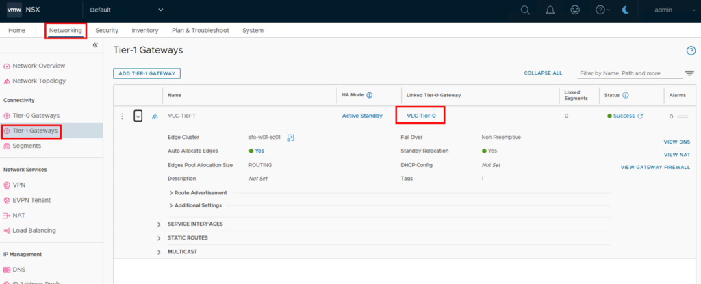
After closing all tabs, we can check whether the T1 router has been created and connected to the T0 gateway. Networking -> Tier-1 Gateways
Via Networking->Network Topology we can also display the whole thing graphically.
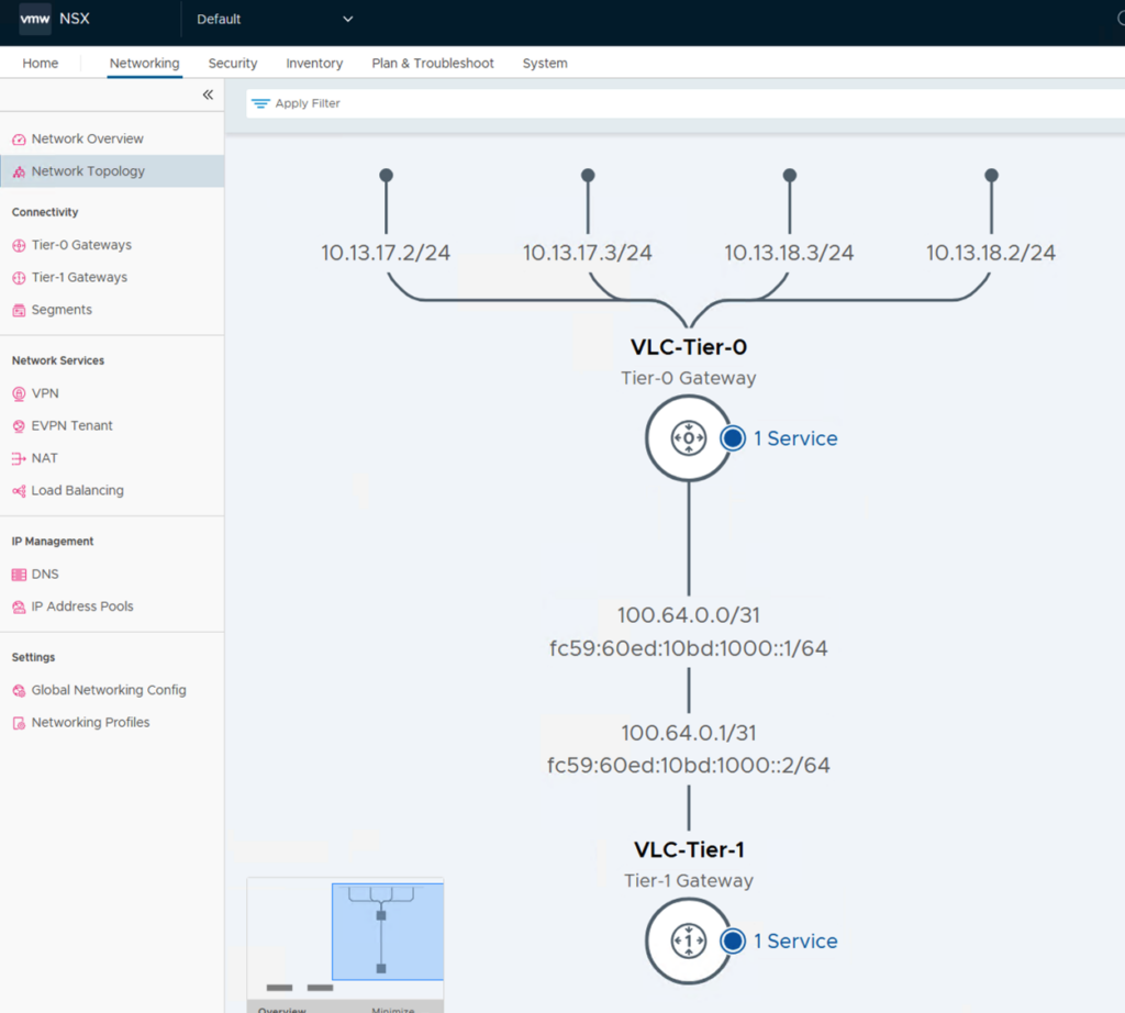
If you’ve gotten this far, you’ve successfully established routing between the NSX overlay and the external data center router!
Appendix – Configuration Overview
The following screenshots show what the SDDC Manager has configured and are intended to provide a better understanding of the background tasks.
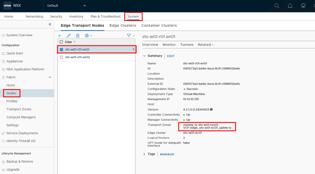
Under the System->Nodes->Edge Transport Nodes tab, we find the two configured NSX Edge nodes. The nodes are located in two transport zones.
The transport zone “overlay-tz-sfo-w01-nsx01” was created when the workload domain was created. This transport zone also contains the ESXi hosts, allowing them to access the NSX Edges in the overlay network.
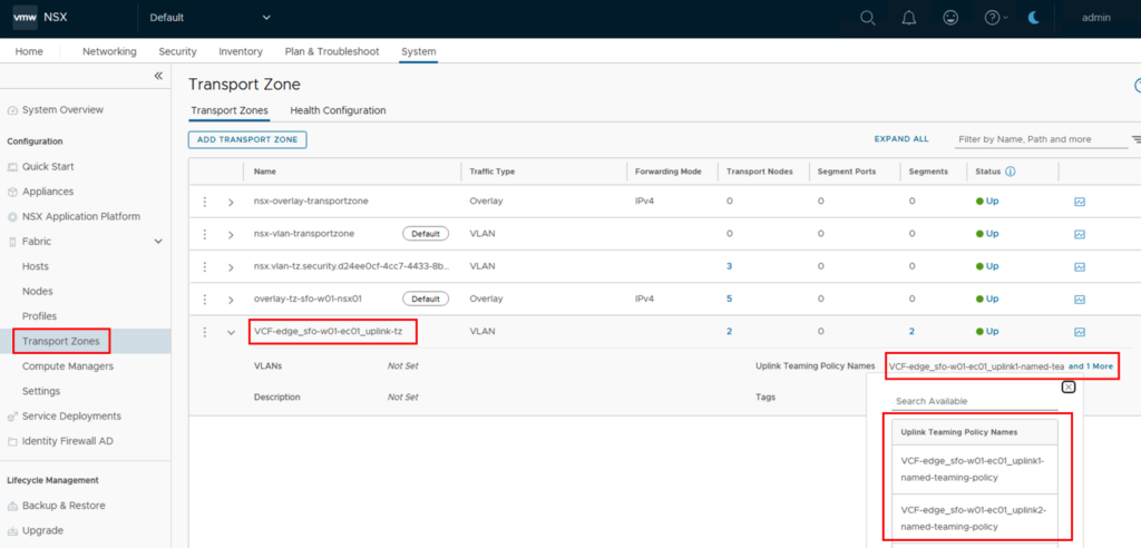
The second transport zone, “VCF-edge_sfo-w01-ec01_uplink-tz,” was created when the Edges were created and is used for the connection to the external data center router (VLAN-based).
The details for the transport zone are located under System->Transport Zones. There, we select the name “VCF-edge_sfo-w01-ec01_uplink-tz.” On the right side, you can see the Uplink Teaming Policy Names.
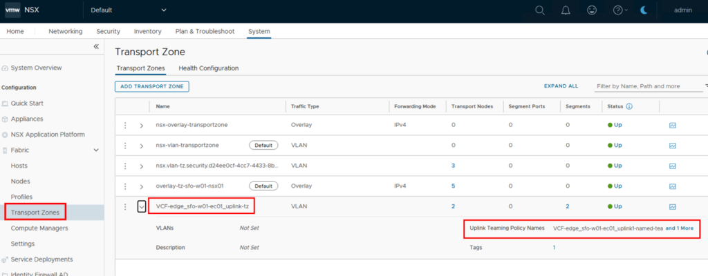
The full information becomes visible when you click on “and 1 More.” You can see that two policies exist, distinguished by their names xxx_uplink1-xxx and xxx_uplink2-xxx.
The exact details can be found under System->Profiles->Uplink Profiles and there under the name starting with VCF-edge_[CLUSTERNAME]_uplink-profile-[VLAN ID] depending on what data was used during installation.
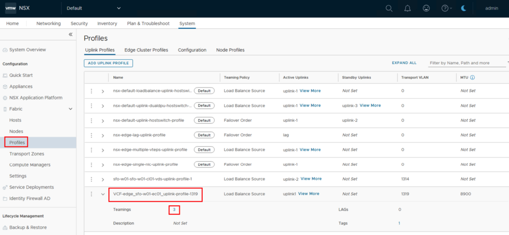
Clicking the “3” next to Teamings opens a new window.
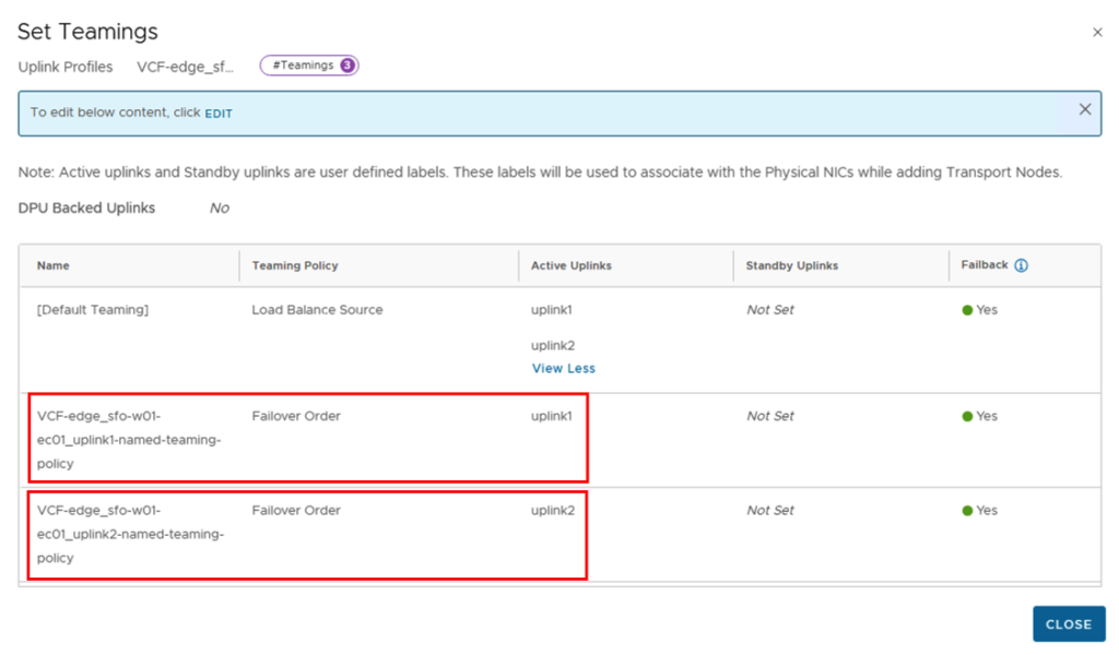
The “Default Teaming” with “Load Balance Source” is used for the overlay connection and uses uplink1 and uplink2 as active links.
Then come two more profiles, each with only one uplink. The VCF-edge_xxx-uplink1-xxx profile uses only uplink1, and the VCF-edge_xxx-uplink2-xxx profile uses only uplink2. These policies are used for the connections to the external data center routers, ensuring clear transit connections between the components.
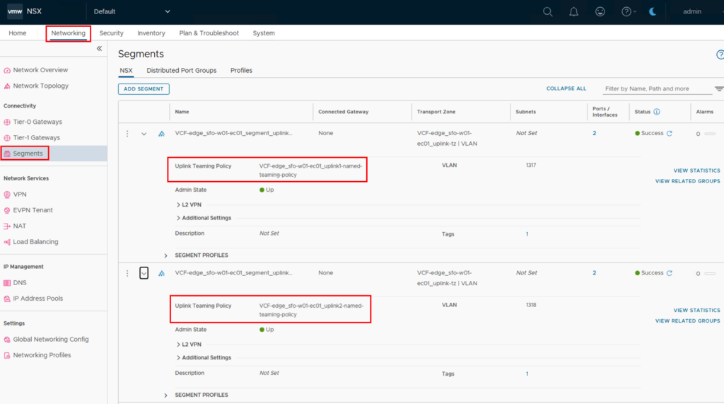
Logical segments are created for the NSX Edge’s external connections, where VLAN information is communicated and teaming policies are defined. This information can be found under Networking->Segments->NSX->VCF-edge_xxx_segment_xxx.
As expected, there are two segments, each with an assigned teaming policy.
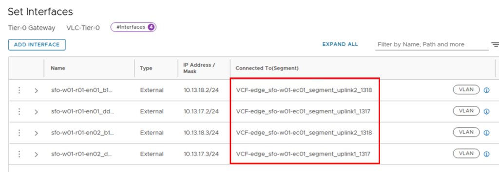
The segments were assigned to the Tier-0 gateway, where the transit IP addresses are also assigned. To do this, go to Networking->Tier-0 Gateways->VLC-Tier-0 and then to “INTERFACES AND GRE TUNNELS.” There, under “External and Service Interfaces,” there should be a “4,” which you can use to view the details.
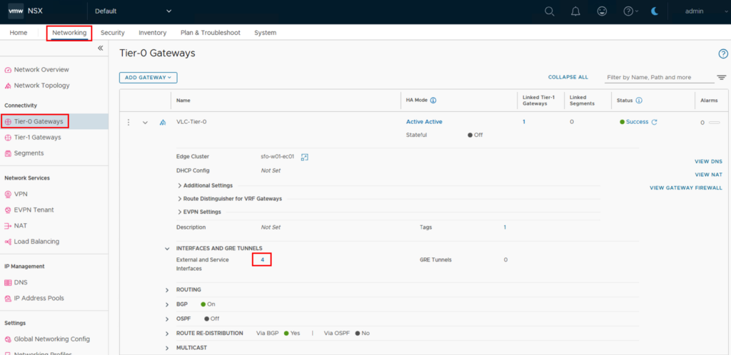
The interfaces contain the mapping to the individual segments and thus to the correct VLANs and the correct uplink.
Summary
Configuring NSX Edges via the SDDC Manager eliminates some configuration steps and reduces complexity, as the SDDC Manager resolves dependencies (transport zones, profiles, teaming policies, etc.). Nevertheless, configuration requires a certain basic understanding of networking, and the installation should therefore be planned carefully and in collaboration with all responsible teams.

- VCF9 NSX-Edge Setup – What has changed - 11. July 2025
- VCF NSX-Edge setup from a network perspective - 2. June 2025
- VCF Workload Domain Setup from a network perspective - 2. June 2025