


This post is also available in:
 German
In my blog “https://vrealize.it/2025/02/10/vpc-networking-with-vcf-nsx/” I discussed the VPC construct in VCF NSX. In this blog I will describe the setup on an existing VCF NSX platform.
Requirements
This blog assumes that vCenter and NSX have already been installed and configured via the SDDC Manager or manually. Here is a small checklist:
- vCenter, Datacenter, Cluster, ESXi + VDS configured
- NSX Manager, NSX Edge nodes, IP routing between T0 gateway and datacenter (external) router configured
- Authentication provider for role based access connected (in my case LDAP)
- If the firewall functions are also to be tested in a VPC, the vDefend AddOn license is required in addition to the VCF license.
Target setup
Below is a diagram describing the target setup.
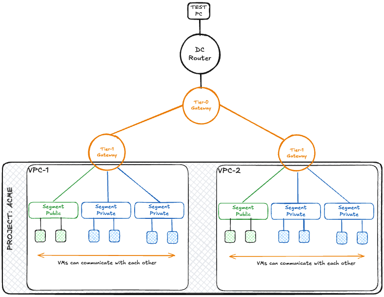
After all configuration steps are completed, there will be a project (tenant) named ACME.
- The VPCs and the segments are created in the project.
- Virtual machines on the “public” segments can be reached from the test PC.
- Virtual machines on the “private” segments can only be reached within the respective VPC.
- Virtual machines on the “private” segments can reach the test PC via NAT (Network Address Translation).
One (or more) IP block(s) are created for both the private segments and the public segments. The public IP block is propagated to the DC (data center/external) router as soon as a public segment has been created. The private IP block is only available on the respective VPC-T1 gateway and is not propagated to the T0 gateway.
- public IP block = 192.168.24.0/22
- private IP block = 172.31.0.0/16
- The test PC has the IP address 172.16.112.53 and ping is allowed
Role Based Access Control (RBAC) is used to restrict access rights to projects and VPCs. The following users are used in my example. The names can of course be chosen individually:
- sylvester = AD user and member of the ent-admin group for NSX and vCenter – for creating projects and setting up public/external IP address blocks
- daffy = AD user and member of the acme-project group – for creating VPCs and setting up private IP address blocks
- tweety = AD user and member of the acme-vpc1 group – user of the first VPC
- porky = AD user and member of the acme-vpc2 group – user of the first VPC
The NSX base configuration
Transport Zones
Geneve overlay tunnels are created for the VPCs. Under System->Fabric->Transport Zones, two transport zones (one overlay TZ and one VLAN TZ) are marked as “Default”. These are automatically selected for the VPCs.
If the VPCs are set up in a different transport zone, this transport zone must be set as the default.
Tier-0 Gateway Configuration
The Tier-0 gateway is connected to an external data center router via BGP via two edges.
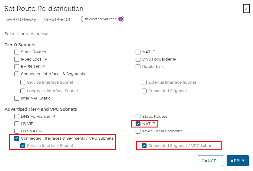
If dynamic routing protocols (BGP/OSPF) are used, “Route re-distribution” must be activated for the VPC networks on the T0 gateway.
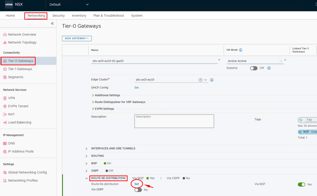
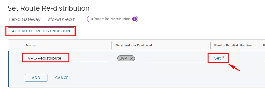
If NSX is only used for the VPCs, it is sufficient to set the checkboxes as shown in the image. If other routes are to be propagated via the T0 gateway, these can of course also be checked.
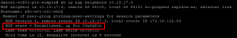
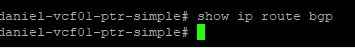
If no other networks are configured at this point, the BGP connection between the NSX Edges and the Datacenter Router will be established, but no routes should have been learned via BGP.
Let’s get started!
Once all preparations are complete, we can start with the VPC configuration. In the current version of NSX, an extra project is required to configure a VPC. This means that there are tasks that the Enterprise Admin carries out and he can have VPC-specific configurations carried out by a Project Admin.
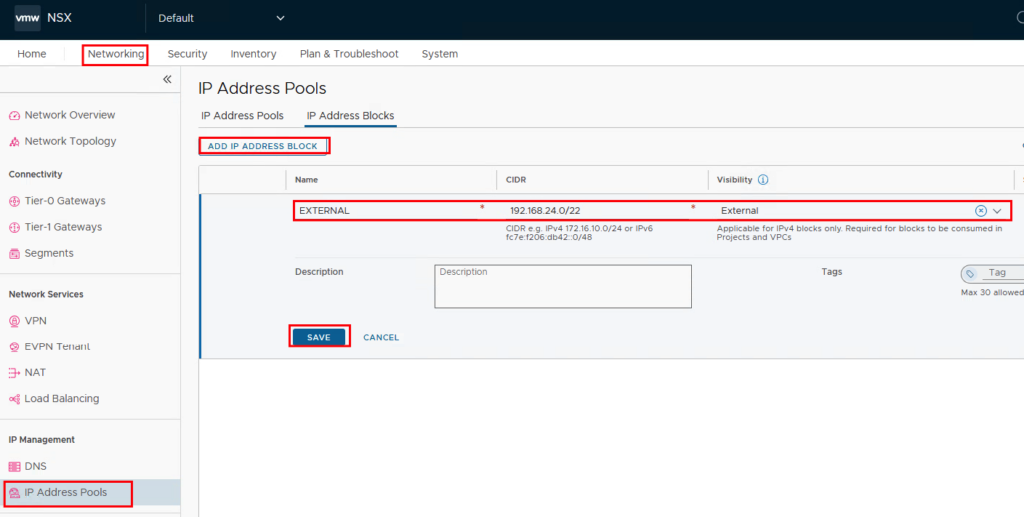
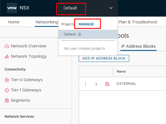
01. Creating the external (public) IP block
The Enterprise Admin determines (together with the network team) which IP address blocks are routed into the corporate network and thus enable access to resources within a VPC. From an NSX perspective, this IP block is called “external”. The defined IP block is created under Networking -> IP Management -> IP Address Pools -> IP Address Blocks -> ADD IP ADDRESS BLOCK. The IP block can be made available either individually for each project/VPC or for multiple projects/VPCs. Depending on the use, the name is either project-related or, as in this image, very generic, as this gives the option of using this IP block for other projects as well.
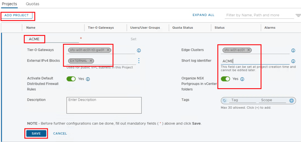
02. Create a project
Next, a project is created and resources are allocated.
Our project called “ACME” uses the existing T0 gateway (several can be selected), an edge cluster and the previously defined external IP block (several blocks can be selected here too).
The short log identifier (maximum 8 characters) helps with later logging. If this is not set, an identifier is generated by NSX.
Depending on whether a firewall is to be used, Activate Default distributed Firewall Rules can be used to specify whether a basic set of rules should be created.
It is recommended to set the switch for “Organize NSX Portgroups in vCenter folders” to “Yes” so that we can also assign the networks to individual users in vCenter.
After the project has been created, you can create quotas (limitations) and assign them to the project.
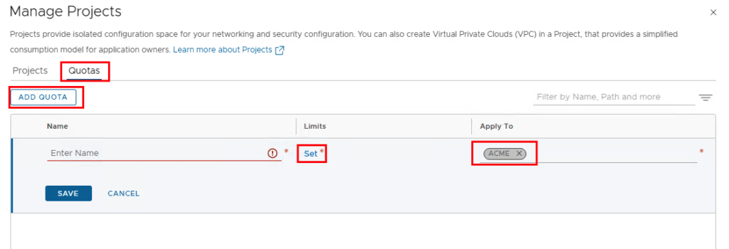
Different limits can be set from network to VPC, it is worth taking a look here, but it would exceed the length of this blog post if I went into all the functions.
03. Add Project Admin to the project
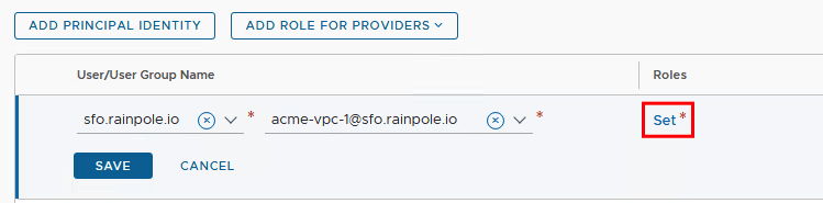
Next, we assign this project to a user or user group. In this example, the users are created in the Active Directory and assigned to the respective groups.
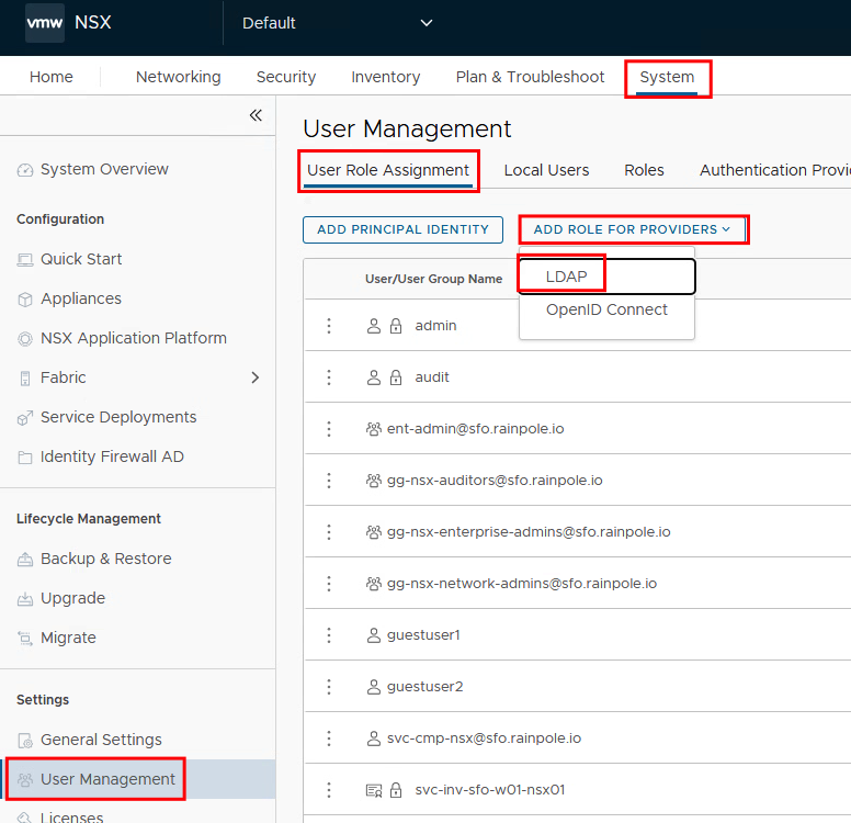
We select the user group (in this case acme-project) and then the roles for this user group.
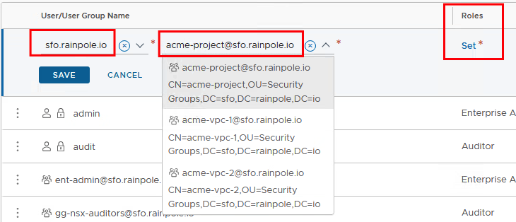
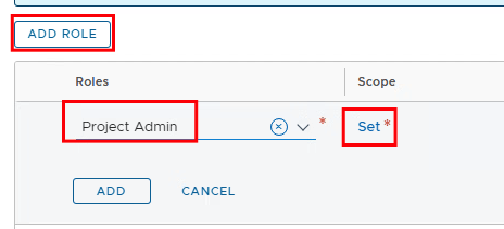
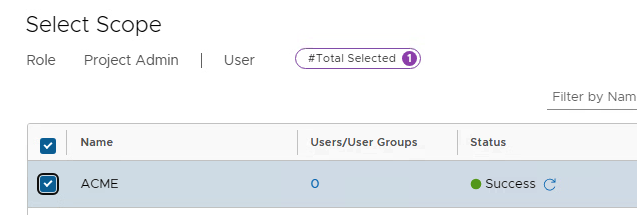
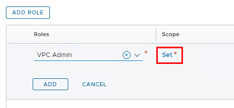
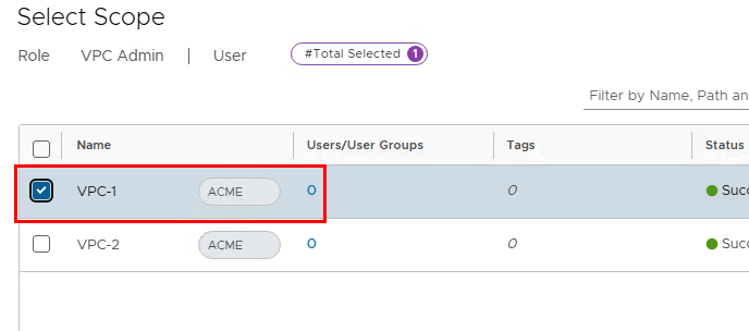
The role is “Project Admin” and the previously created project is selected as the scope.
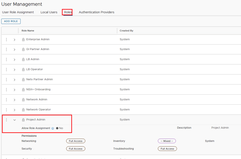
Depending on whether the Enterprise Admin or the Project Admin should set the permissions of the VPC users, the Project Admin must be given the “Role Assignment” permission under Roles.
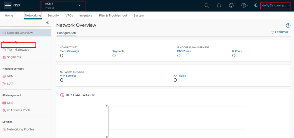
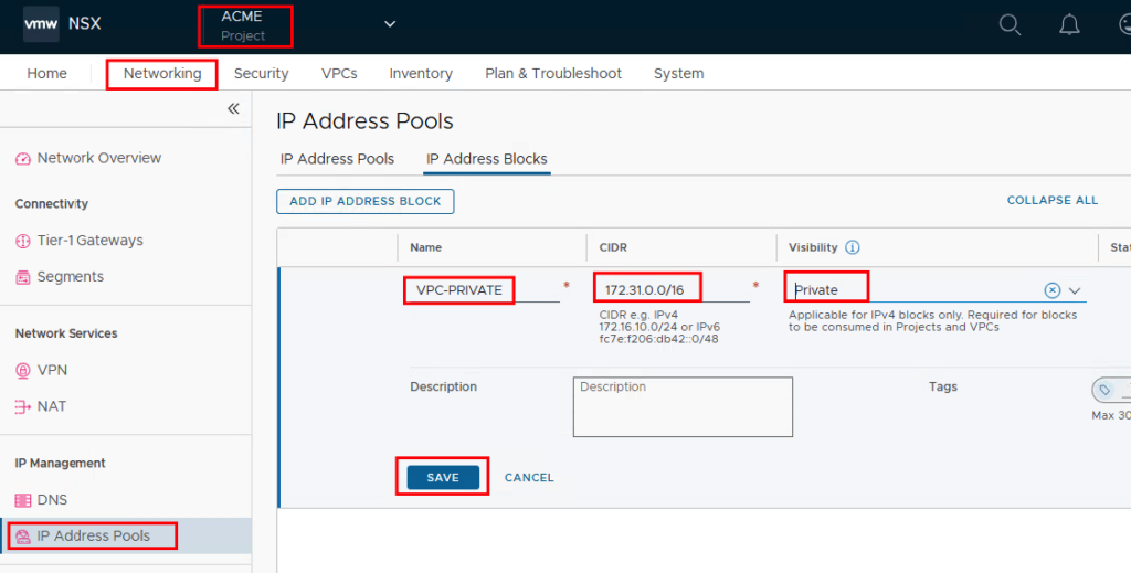
04. Login as Project Admin and create the private IP block
As soon as you log in as a project admin in my example with the user Daffy, you will see that you are directly in the project and the Tier-0 gateway is no longer available. You will also quickly notice differences in the other tabs.
For the VPCs, a private IP block is created in the project that is used for the VMs that do not need to be accessible outside the VP. In this example, the segments in a VPC can use a network from the subnet 172.31.0.0/16.
05. Creation of VPCs
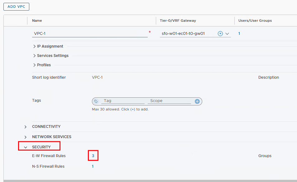
Now everything is ready to create the two VPCs. To do this, we switch to the newly added “VPCs” tab and click on “ADD VPC”.
Next to the name of the VPC, we select the T0 gateway again, take the previously created IP blocks for the external and private areas and then decide whether NSX should also be the DHCP server for the connected VMs in this VPC.
If you choose DHCP from NSX, the DNS server IP address is required.
The following service settings determine whether firewall rules should be created and whether the VMs in the private segments can communicate externally via a NAT rule. This is helpful if services outside the VPC need to be accessed. This can be a DNS server, NTP server or other services. Since we want to test later whether the VMs can also communicate externally, we leave the settings at the default values.

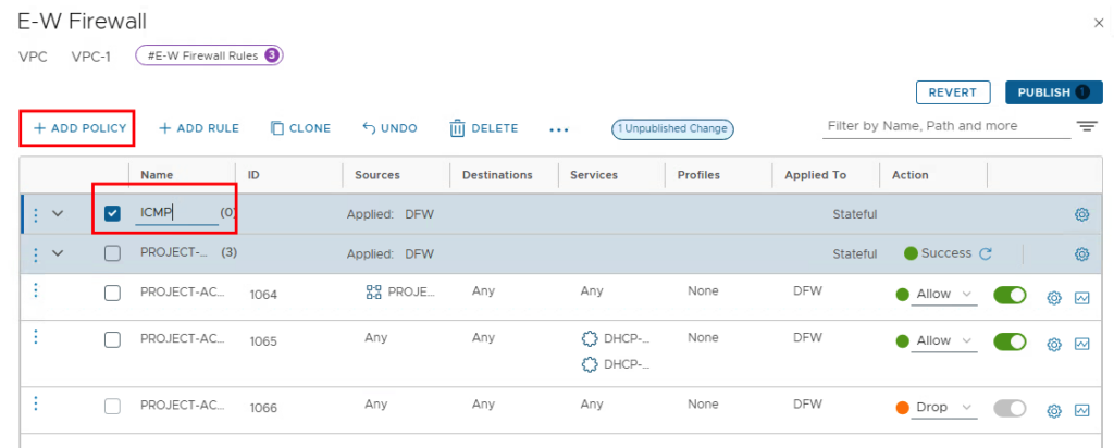
If the vDefend AddOn is licensed and you have decided to leave the checkbox for “Activate Default E-W Firewall Rules” activated, you should be aware that communication to the VPC is prohibited without an allow rule. In order to be able to test at a later point in time whether the VMs in the VPC can be reached from the test PC (outside the VPC), at least ICMPv4 must be allowed on the VPC. To do this, the security area in the VPC is expanded and ICMP is added to the E-W Firewall Rules.
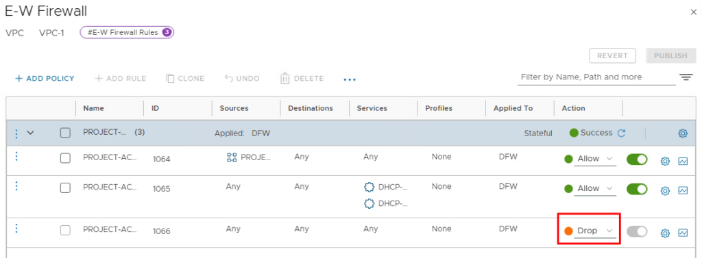
The default rule (ID:1064) allows communication from all VPC members (PROJECT-ACME-VPC-VPC-1-default) to all targets, both inside and outside the VPC. In addition, the DHCP service is enabled. The last rule (ID:1066) prohibits any further communication.
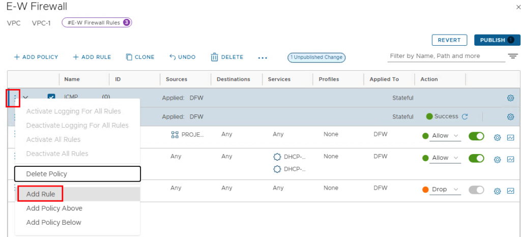
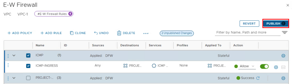
Using “ADD POLICY” we now create a policy above the default policy. We can enter “ICMP” as the name.
We then create the rule “ICMP-INGRESS” in the policy.
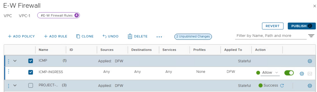
The source remains “Any” and the destination is edited. The predefined group for the VPC members with the name “PROJECT-ACME-VPC-VPC1-default” is available for selection.
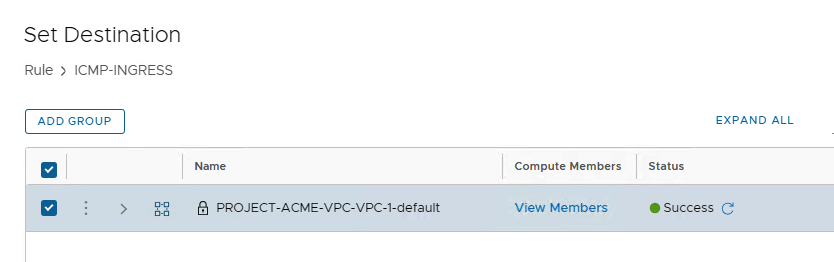
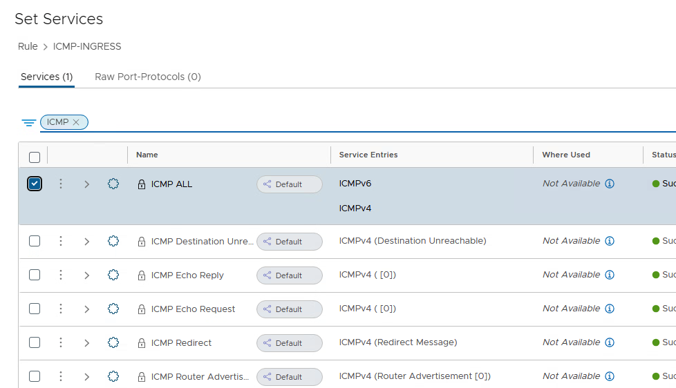
Then select “ICMP ALL” in the “Services” field (this allows both IPv4 and IPv6 addresses to be used)
To ensure that the firewall rule does not waste unnecessary resources and is only applied to the VMs that are present in the VPC, the “Applied To” field can then be applied to the “PROJECT-ACME-VPC-VPC1-default” group.
In the last step, the firewall is activated with the “PUBLISH” button.
After VPC-1 has been successfully created, another VPC can be created with the same settings (except the name ;-). This step is optional and is only required if you want to test the connections between two VPCs.
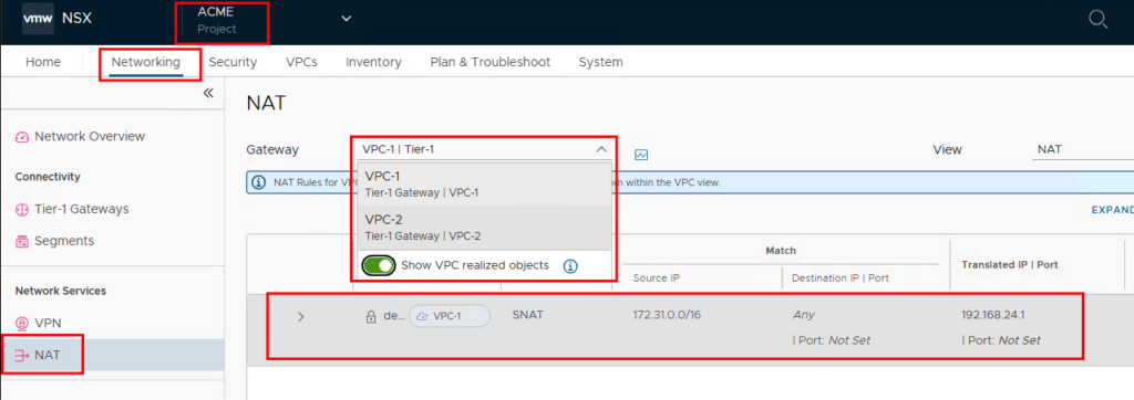
As soon as a VPC has been created, a Tier-1 gateway is automatically created and a SNAT entry (Source Network Address Translation) is created for the VMs that are connected to a private segment. The IP addresses are taken from the external IP pool. The SNAT entries can be viewed at the project level under NAT if “Show VPC realized objects” is selected.
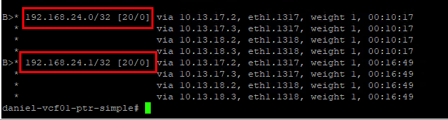
These networks are also learned via BGP on the external data center router.
06. Assign VPC access authorization
As we did before for the project, we now want to give different user groups permission to access the respective VPC. To do this, we log in again with the admin user, since we did not give the project admin permission to authorize VPC users.
This time we first select the group acme-vpc-1 and then follow the same procedure for acme-vpc-2.
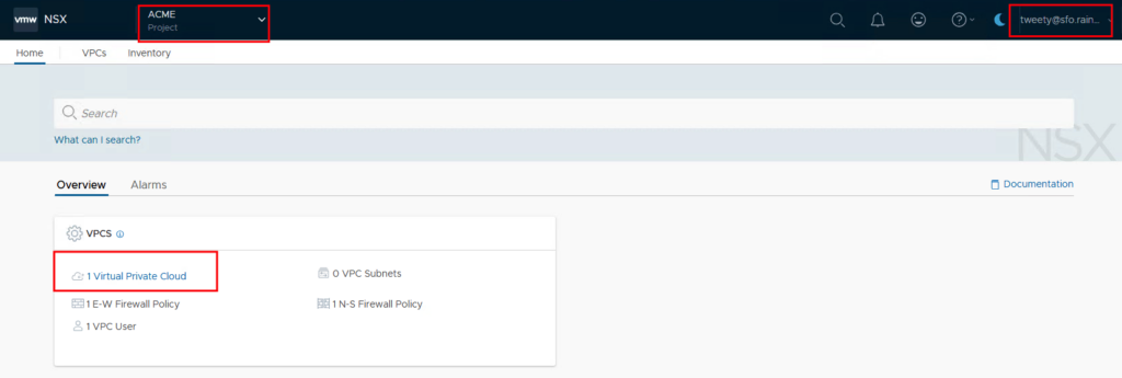
After that we can log in as VPC-1 users.
07. Creating VPC networks
Once you log in as a VPC user, many configuration options disappear.
We switch to the VPCs tab and edit the VPC assigned to us.
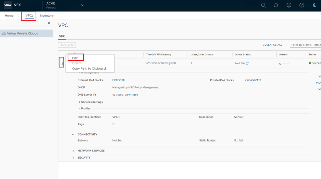
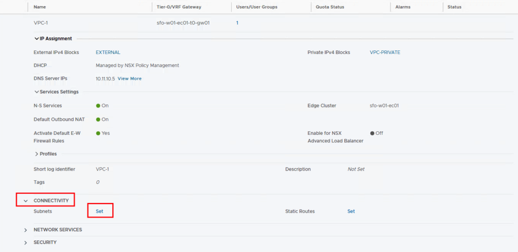
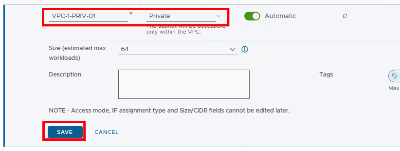
Then we go to Connectivity and create a new subnet
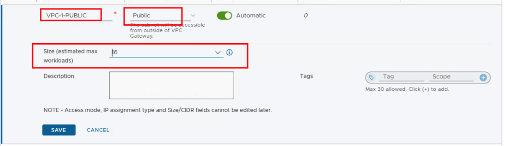
First, we create a segment that should also be accessible from outside. We therefore select Public as the access mode. Depending on how many VMs are to be connected to this segment, you select the size (estimated max workloads). !!Attention!! 4 addresses are reserved by this network. This means that if I select 16, I can use 12 addresses.
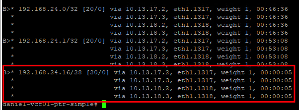
Once the configuration is saved, an IP network is created from the external IP pool and propagated to the data center router via BGP.
Next we create two private networks. This time the access mode is of course “Private”
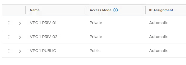
We repeat the process with the VPC-2 user and also create a public and 2 private networks.
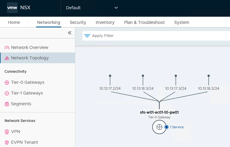
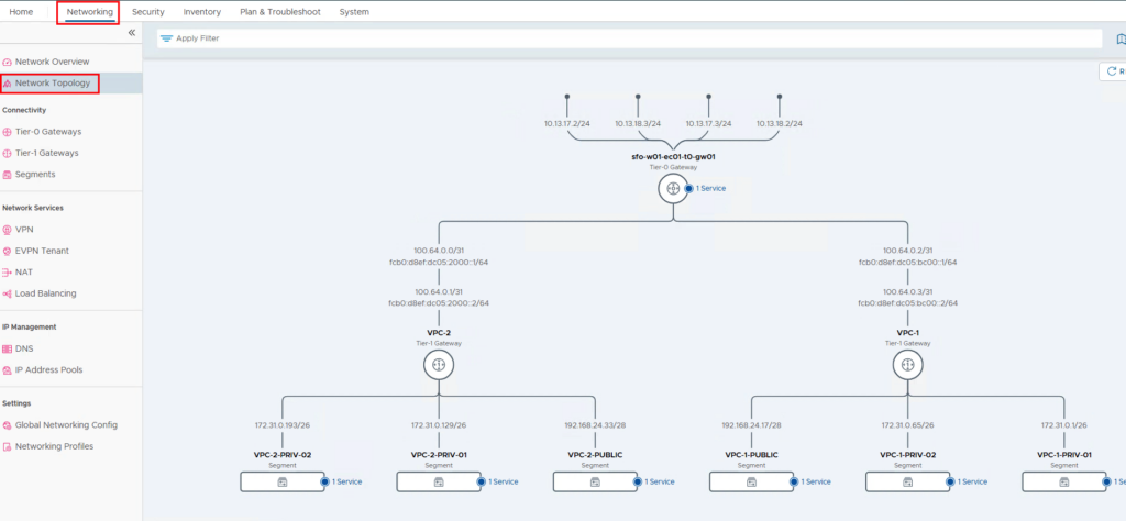
If you now look at the network topology as an enterprise administrator, you will see the networks and the Tier-1 gateways that are connected to the Tier-0 gateway.
08. Create vCenter users and assign them to VPCs
!!The following steps are carried out for the VPC 1 and VPC 2 groups!!
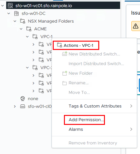
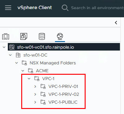
Everything is now prepared in NSX and the VPC users can add or delete additional networks. Now it is time to open the vCenter to see whether the networks are visible there and to store the users here accordingly. To do this, we log in to the vCenter with a vCenter administrator. In the network tab you can see a folder called “NSX Managed Folders” and under this folder the two VPC folders with the associated networks.
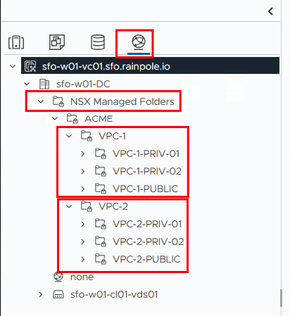
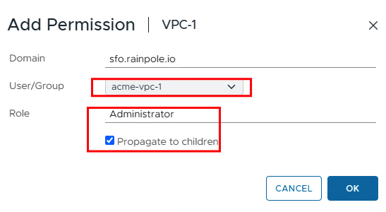
If the vCenter is also connected to the Active Directory, we can add the permission for the VPC-1 group on the VPC-1 folder (by right-clicking). The permission should then also be inherited by the children.
In order for users to be able to create VMs in their “VPC” or resource pool, a few more steps are necessary.
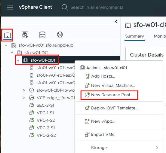
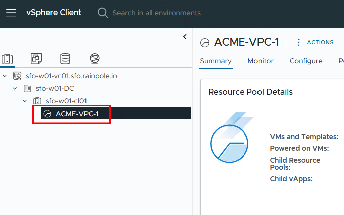
Create Resource Pool
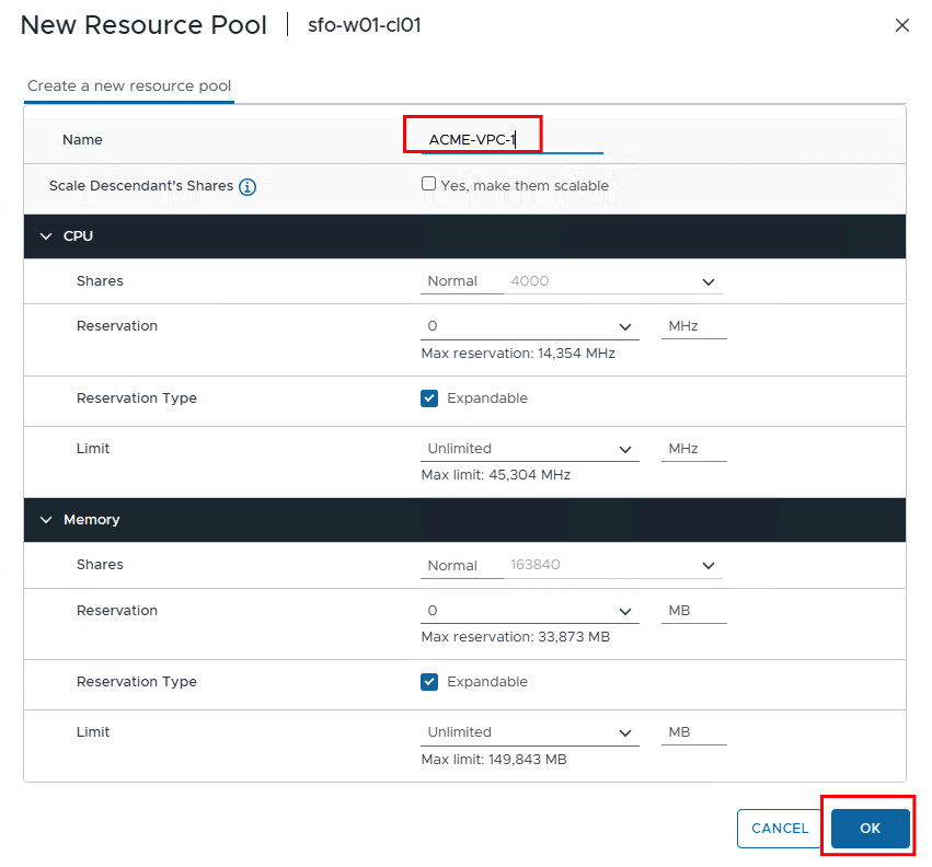
The resource pools for VPC 1 and VPC 2 are now created under the Hosts and Clusters tab. The VPC user then receives the right to configure everything there as an admin. At this point, you could also set restrictions on how many resources are available to the pool.
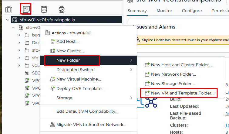
Create VMs and Templates Folder
Then a VMs and Templates folder must be created and this also receives the permissions.
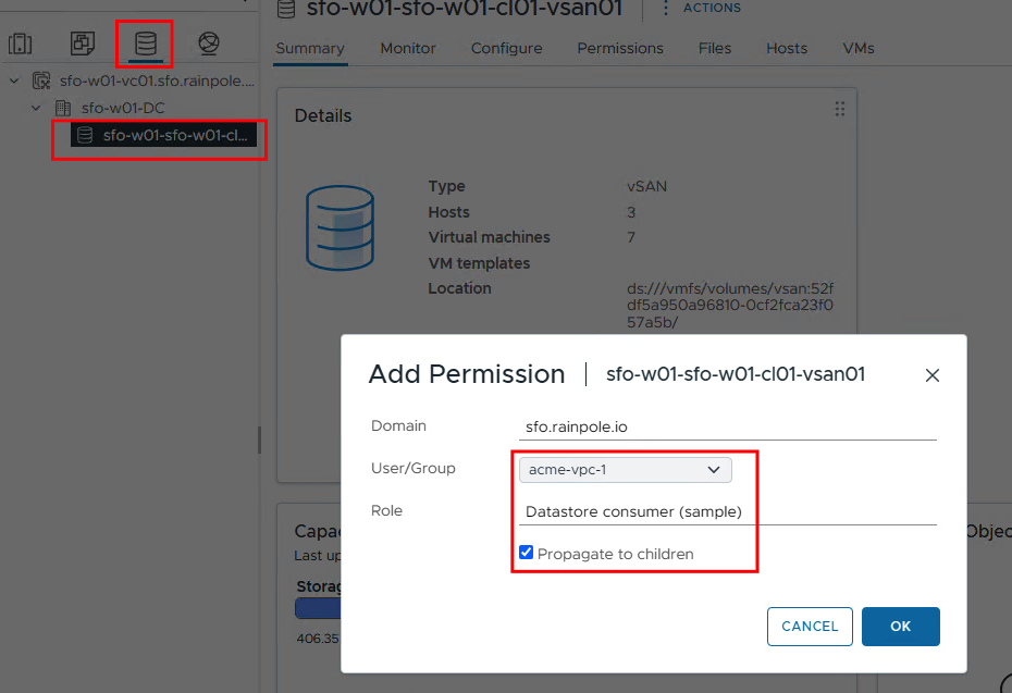
Datastore Access
And finally, we add the users as “Datastore Consumers” to the respective datastores that are allowed to be used.
09. As a VPC user, create VMs in your own VPC
After all the settings have been made in the vCenter, we can next log in to the vCenter with one of the two VPC users.
The VPC admin can only see his resource pool…
…and only his networks
The VPC user can now create virtual machines or upload OVA files and only select the networks that are assigned to their VPC. Since we use DHCP over NSX, the VMs should not have a static IP but should obtain an address via DHCP.
I will skip the creation of virtual machines and assume that this knowledge is available.
10. Testing
Now that the VMs are installed, at least two VMs should be installed in a VPC (one in the public network and one in the private network).
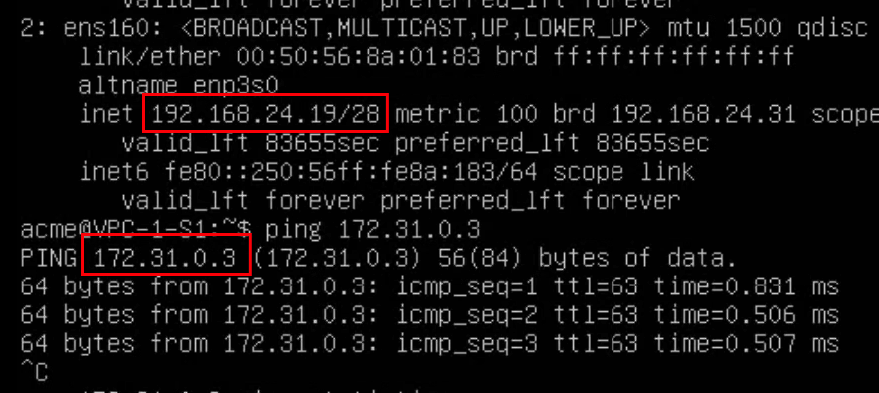
The VM VPC-1-S1 is located on the network segment VPC-1-PUBLIC and has been given the IP address 192.168.24.19. As expected, this address has been taken from the range that we previously selected as external IPs.
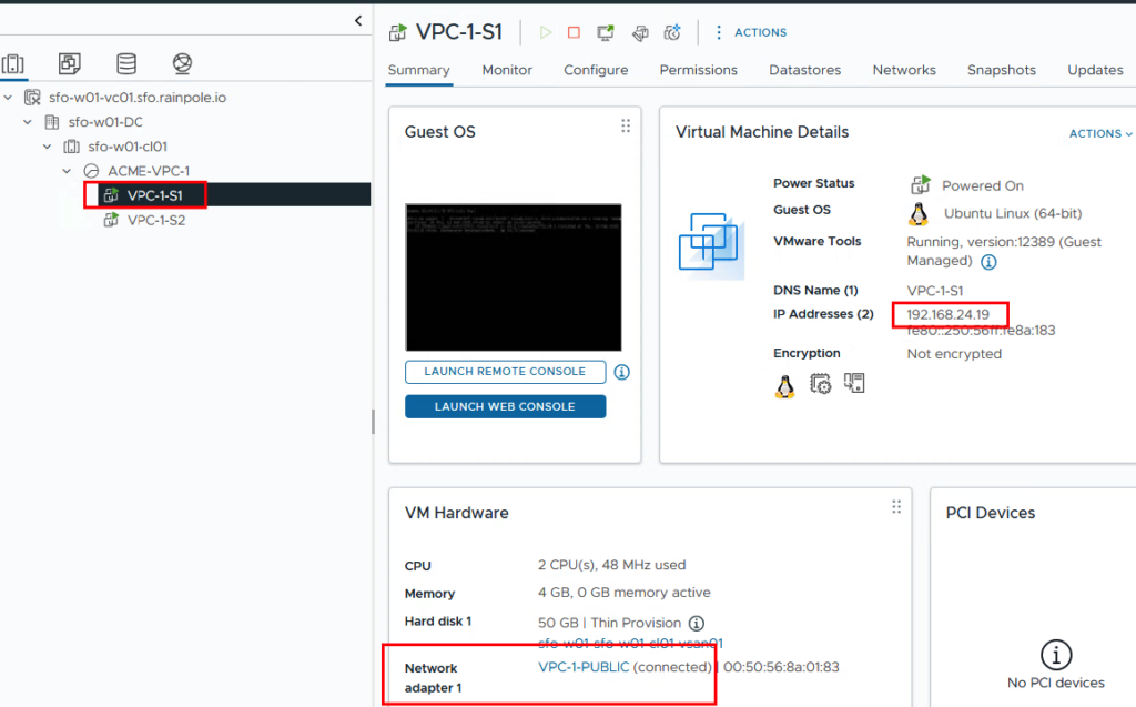
Test 1 – Ping from test PC (external) to VPC-1-S1 (192.168.24.19)
If the ping is not successful, you should check whether there is a firewall that could block this ping. (VPC Firewall, NSX Firewall, Project Firewall, Datacenter Firewall)
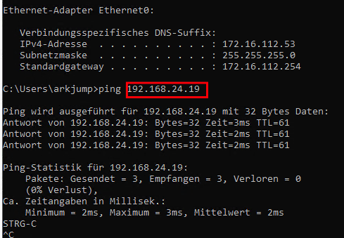
After the successful ping, we look at the second VM.
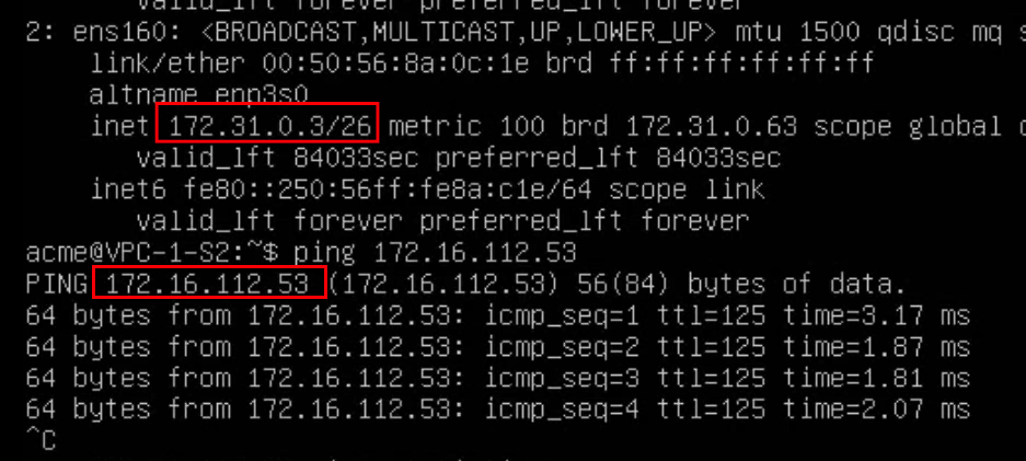
The VM VPC-1-S2 is located on the network segment VPC-1-PRIV-01 and has been given the IP address 172.31.0.3. We previously defined this IP address range as the private range that is not routed outside the VPC.
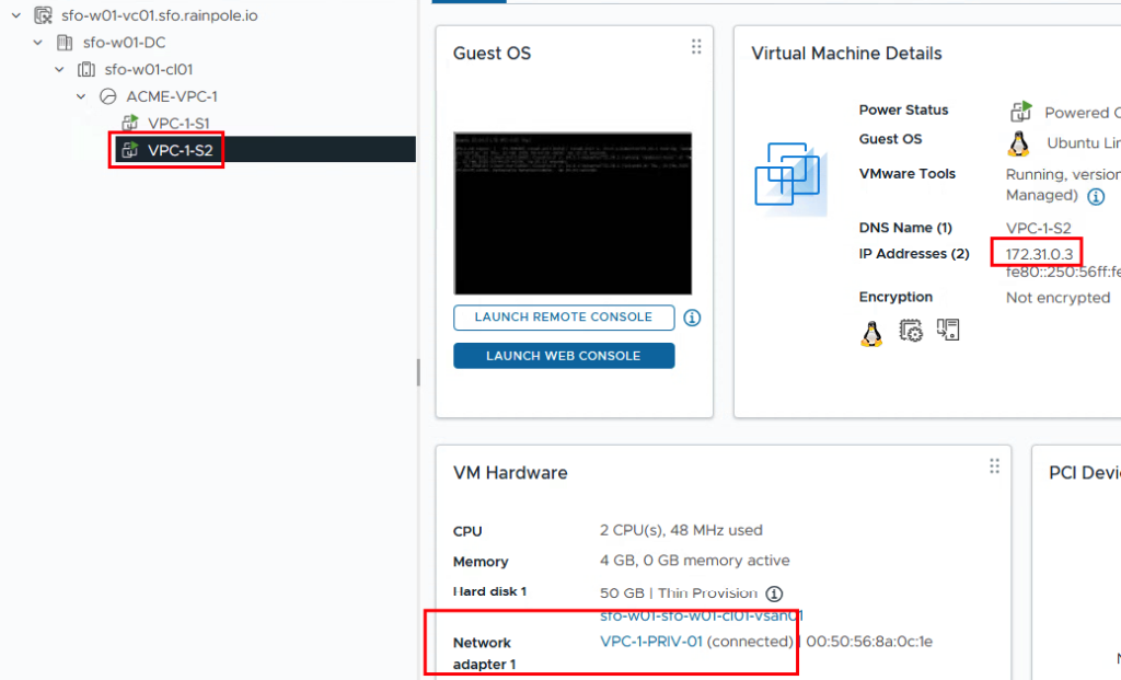
Test 2 – Ping from test PC (external) to VPC-1-S2 (172.31.0.3)
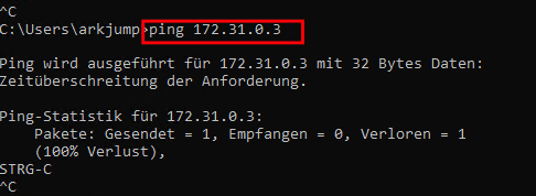
As expected, the ping is unsuccessful, even though no firewall is blocking it. Since this network is not routed at all, it cannot be reached outside the VPC.
Test 3 – Ping from VPC-1-S2 (172.31.0.3) to test PC (external 172.16.112.53)
A ping to the test PC is possible from the network 172.31.0.0/26 because the PC has an outgoing NAT rule and thus the packet can be transported.
Test 4 – Ping from VPC-1-S2(172.31.0.3) to VPC-1-S1(192.168.24.19)
The ping is successful for two reasons. Firstly, because the destination has a public IP and secondly because both servers are in the same VPC.
Does the test also work the other way around?
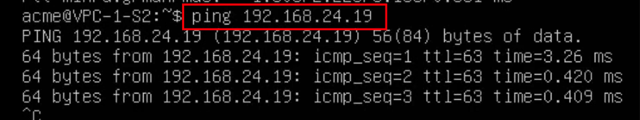
Test 5 – Ping from VPC-1-S1(192.168.24.19) to VPC-1-S2(172.31.0.3)
The ping is also successful because both servers are in the same VPC and are therefore connected to the same T1 gateway.
Summary
Setting up a VPC, like anything else, needs to be planned and requires a little preparation. However, once the VPC is configured, the VPC user can manage their own environment without putting the network infrastructure at risk. This can reduce the workload on the network team and the security team.
I’m happy to accept comments and suggestions!

- VCF9 NSX-Edge Setup – What has changed - 11. July 2025
- VCF NSX-Edge setup from a network perspective - 2. June 2025
- VCF Workload Domain Setup from a network perspective - 2. June 2025